|
revised 2nd of Oct 2011 PM added Machlett tube
measurements, Dentron, rules, and warnings
revised 23 Feb, 2013 for some minor wording clarity
|
The purpose of this page is to present the full unedited
Eimac Filament Management program to readers as applicable to amateur radio
amplifier systems, and to show proper filament voltage measurement techniques
before people injure or electrocute themselves, diminish amplifier performance,
or damage tubes.
Rules for Setting Filament Voltage
No exceptions. Before setting filament voltage we must know
and account for the following:
1.) Proper filament voltage range, or
best target voltage. This either comes directly from tube data sheets or
directly from the equipment manufacturer.
2.) RMS voltage at tube pins in a fully
warmed amplifier for a given power line voltage. This has to be true RMS
voltage, not a calculated RMS from a typical averaging meter. With higher
current filaments, it is critical to know the voltage on the tube pin.
Knowing voltage some distance away, even a few inches, is not correct.
3.) Full power line voltage range at
the equipment location.
4.) Filament RMS voltage variation
while the equipment is operating under maximum power, or at idle. This is
critical.
|
Warning:
Low filament voltage can result in faster emission
loss than excessive voltage. Do not assume we can blindly adjust
filament voltage to some nominal voltage without knowing and accounting
for all of the above rules!
For example, Dentron amplifiers normally have much
higher filament voltage than acceptable range. They also have very poor
filament regulation with power supply loading, typically varying 3% from
no load to full load on the high voltage. If we only account for minimum
line voltage under no transformer load and set for minimum filament
range, the filament will almost certainly fall below minimum. This
increases IMD (splatter) and can shorten tube life more than too much
voltage!
If instructions set voltage without following the
above rules, they are wrong and can cause damage.
|
Filament Voltage
Most tube data sheets specify an allowable range
of filament voltage. This voltage range, without question, satisfies warranty
requirements and assures proper performance as related to the filament. We can
move voltage outside that range only if the manufacturer approves, or if we
properly verify performance. Most important and often overlooked, there
are minimum and maximum voltages! While generally not mentioned on
amateur radio forums and web pages, excessively low filament or heater voltages
can actually be more deleterious than needlessly high filament or heater
voltages.
Minimum voltages are especially critical in oxide-cathode
tubes. While operation above allowable range deteriorates the very long term
emission life to perhaps 60% or so for every 5% above nominal
voltage, operation below safe minimum voltages will usually destroy the tube in
surprisingly short order. This includes tubes like the 8877/3CX1500A7,
3CX5000A7, and 3CX800A7. I’ve occasionally seen amplifiers that have been
modified to reduce tube filament voltage with repeated short tube life. One
amateur amplifier’s 8877 was set at 4.2 filament pin volts, and went through a
new tube in less than one month of casual amateur operation. The brand new tube,
because of low voltage poisoning, had no warranty.
Directly heated tubes (those without heater warm-up time) are
more tolerant of low voltage, but not immune. In some cases, a filament
management program can extend directly-heated power grid tube, but not
always. One private website, and the October 2011 QST Magazine (parroting that
private website), make grossly exaggerated claims of increased tube life through
reduction of filament voltage to an arbitrarily created value. Unfortunately,
not only are life increase promises greatly exaggerated; the target voltage is
selected incorrectly, and the article’s measurement methods are wrong. The
result is SSB bandwidth and tube life can be compromised from excessively low
filament voltage.
To comply with tube filament voltage management, the filament
must be regulated within +- 3% and a host of other criteria must be met. Here is
what Eimac says, in Eimac’s own unedited words:
|
NOTE: If the filament voltage cannot be
regulated to within ± 3%, the filament should always be operated at the
rated nominal voltage specified on the data sheet.
It should be noted that there is a
danger to operating the emitter too much on the cold temperature side.
It may become poisoned. A cold filament acts as a getter; that is, it
attracts contaminants. When a contaminant becomes attached to the
surface of the emitter, the affected area of the emitter is rendered
inactive, causing loss of emission.
|
If we cannot meet all criteria,
we should use nominal rated voltage. Nominal rated voltage is given in every
tube manufacturer’s data sheet, and cannot be arbitrarily rewritten to a new
value at whim.
Why a Voltage Range?
Power line voltage varies seasonally and with local time. Most
amateur (and many commercial) products, because of size, weight, or cost, cannot
use regulated AC filament supplies. Directly heated cathodes also do not work
well on DC supplies. A DC supply biases one end of the filament more negative in
relationship to grids, and this can unevenly distribute emission current. This
is especially problematic in higher voltage filaments with low bias tubes.
Most amateur and many commercial amplifiers or transmitters
employ simple step-down filament transformer systems. While filling a cost and
space limit, these systems cause filament voltage to vary with power line
voltage and transmitter power level changes. Better designs account for filament
voltage variation as supply mains (power line) voltage varies, as well as wiring
temperature and load power demand variations. Designers should always select the
best possible filament voltage to power line voltage relationship, and this
relationship must include
all causes of filament voltage change over time.
Eimac generally considers +5% or -5% of nominal voltage as an
acceptable filament voltage range. Looking at data sheets for the 3-500Z, we see
nominal voltage is 5.0 volts RMS, with permissible range between 4.75 and 5.25
volts. The 3CX1200A7 filament is 7.5 volts + – .37 volts, again about 5% plus or
minus. Other manufacturers are similar in tolerance. National 811A and Cetron
572B tubes use 6.3 volt filaments, with a specified voltage tolerance of +
– 0.3 volts. Once again, tolerance is roughly + – 5% of nominal filament
voltage.
If safe filament range is unspecified, +- 5% is a
reasonable assumption. It will not be the end of the world if the filament goes
outside that range in amateur use, but we should make every reasonable effort to
stay within that range. We should always remember that tube life is a
combination of many things. Depletion of the
filament’s ditungsten-carbide layer is one of most frequent problems in
broadcast, but one of the least frequent problems in amateur service.
Power Line Stability
In the USA, power line regulation standards vary with
suppliers. In general,
power mains are supposed to vary less than ~8% worse case. This is nearly
the same as saying line voltage typically varies less than
+4% or -4% of some nominal voltage. Line voltage variations fit
well with tube filament voltage ranges.
We can, of course, have voltages outside that range. It is a
good idea to minimize additional voltage drop inside the house, since voltage
drop varies with load power and load power varies with the power delivered to
the antenna system!
It is impossible to adjust filament voltage properly unless
the adjustment procedure includes long term measurement of power mains voltage
variations, both in system delivery and under varying equipment current demand.
If we see any adjustment procedure in an unregulated filament supply system that
does not include allowance for power mains variations or a powerline voltage
maximum or minimum limit, the procedure is without value. This is a litmus test
for validity.
Tube Life and Amateur Radio Use
In the amateur radio fraternity, we find occasional specific
claims that a specified reduction in filament voltage produces a specific tube
life increase. This information seems to all go back to a single source, an
amateur radio operator in California. It appears he extracted a small slice of
data from Eimac filament management programs (extending tube life in AM and FM
broadcast service), and spun the small extraction into his own cast-in-stone
tube life rule. This rule is blindly repeated as coming from Eimac, and often
exaggerated even more in the rewording process.
In this conversion from AM/FM broadcast to amateur use,
differences in operation and other more common failures were ignored. Also
ignored were multiple warnings and test procedures accompanying Eimac’s Filament
Management Program, and powerline variations, and other much more common
failures.
There are overwhelming differences between AM/FM broadcast and
amateur operation. Let’s compare a few typical AM/FM broadcast operating
parameters directly affecting tube failures to common amateur systems and
components:
Typical Operating Conditions or Typically Expected Use
Comparison
| Operating problem |
AM broadcast |
FM broadcast |
Amateur SSB |
Amateur CW |
Filament temperature cycling shock. increases
chances of open or dislocated filaments |
less than once every 168 filament hours |
less than once every 168 filament hours |
once every 4 filament hours |
once every 4 filament hours |
| Internal element heating and cooling cycles. increases chances of element alignment or out-gassing issues |
less than once every 24 filament hours |
less than once every 24 filament hours |
constantly while operating |
constantly while operating |
Emission demand near peak values. prevents
reducing filament voltage without increased distortion or splatter, and
increasing cathode contamination |
almost never |
never |
common |
never |
Non-use deterioration of vacuum. increases chances
of arcing in glass tubes |
rare |
rare |
many hours a year |
many hours a year |
Approach or exceed internal tube element temperature
limits. increases chances of internal gas |
never |
never |
fairly common while tuning |
fairly common while tuning |
Filament hours per year. increases yearly filament
emission depletion failures |
8750 |
8750 |
500 |
500 |
Tube Quality. uncontrolled failures due to poor
tube materials, processing, or construction |
Expensive USA or European tubes with excellent quality, good processing control methods.
Reliable |
Excellent tube quality, good processing control methods.
Reliable |
Import cheap tubes. Less-than-ideal material, processing, and testing methods and
control |
Less-than-ideal material, processing, and testing methods and
control |
Considering the profound differences listed above, it’s easy
to see why tubes in broadcast stations benefit from complex filament management programs. Differences between commercial and amateur use change the
type of tube failures each service experiences.
Broadcast yearly filament hours are about 15-20 times higher
than nearly all amateur yearly filament hours, and broadcast tubes are babied
with almost no thermal shocks or thermal cycles. Commercial broadcast services wear tubes down through emission
loss more than anything else.
Tubes in amateur
radio applications have much different stresses and running hours, and will not benefit from a rigid, complicated,
filament management program. Most amateur amplifiers take
decades to equal one-year broadcast station filament hours. The constant thermal
cycles and long periods of storage are a lot tougher on
tubes. Amateur tubes are also almost always lower-quality foreign tubes.
Because of the profound operational and tube manufacturer
quality, amateur tubes have virtually zero failures from excessive
filament temperature. This includes amplifiers running far above recommended maximum
filament voltage. For example, Dentron amplifiers commonly run 15% or more over
recommended filament voltage, yet very few older Dentron tubes suffer emission failures. Many
Dentron amplifiers are still using 1970-era tubes, even though Dentron filament
voltages are well out of allowable range and Dentron tube cooling is generally
pretty poor. This doesn’t mean we should run needlessly high filament voltages in
amateur service, or not correct grossly out-of-tolerance filament supplies, but
it shows how little amateur service stresses emission life. Of course we won’t
likely be so fortunate when older tubes are replaced with modern imports, but
that is a tube quality
issue.
If we want to reference an Eimac paper and make changes, we
should understand and reference the paper fully and differences between the
service discussed in the paper, and the
different service we are attempting to apply a document to. We should
follow
everything the paper tells us to do, and not extract, exaggerate,
and misapply one or two lines from pages of information.
Comparison of New 3-500Z Tube Samples
-35 dB PEP IM3 was chosen in the tests below. -35dB PEP is
“cleaner” than almost all modern solid state radios, leaving the radio as the
primary source of distortion.
Measuring brand new 3-500Z and 3-500ZG tubes
produced the following results:
-35 dB PEP IM3 / Saturated Power
Filament voltage regulated at 5.25 volts
High voltage 3000 volts
Drive power at cathode adjusted to obtain saturated power, or
-35 dB PEP 3rd order IMD power
Grounded Grid
| Type |
Saturated power PEP |
PEP @ -35 dB PEP IM3 |
| China 3-500Z |
950 |
775 |
| Eimac 3-500Z |
1050 |
925 |
| Machlett 3-500ZG (1) |
1050 |
900 |
| Triton 3-500Z |
1100 |
950 |
| Machlett 3-500ZG (2) |
1200 |
975 |
| Amperex 3-500ZG |
1210 |
1050 |
Minimum Filament Voltage for -35 dB PEP IM3
-35dB PEP 3rd order, 3000 volts anode. 850 W PEP target (AL80B
specification)
| Type |
Min filament V RMS |
PEP @ -35 dB IM3 |
| China |
5.25 |
800 |
| Machlett (1) |
4.8 |
850 |
| Eimac |
4.7 |
850 |
| Triton |
4.7 |
850 |
| Machlett (2) |
4.7 |
850 |
| Amperex |
4.5 |
850 |
Multiple samples of the same type except Machlett were not available. The
Matchlett tubes were the same code date and production run, and matched each
other for quiescent current. This
does show, for brand new tubes of various brands, minimum allowable filament voltage
varies considerably for a
given maximum power and distortion.
Dominant 3-500Z Failures in Amateur Service
When Eimac manufactured 3-500Z tubes, the dominant failure was
cocked anodes. Welds on one side of the anode would simply let go. Opening a
tube, it was evident many welds never fully penetrated the metal. These failures
appeared to be periodic weld problems confined to well-defined production
batches. The vast majority of tubes, however, would last dozens of years in
amateur service. Emission failures over very long usage hours,
which is the only thing filament voltage influences, were
statistically zero. In order, Eimac 3-500Z failures were:
- Cocked or detached anodes, often clearly visible when the
shipping box was opened, sometimes only appearing after many anode thermal
cycles
- Broken grid wires, again often visible when the shipping
box was opened
- Gas, generally after years of use mixed with long periods
of sitting unused
From 1982 until Eimac ended glass tube production, fifty to
one hundred 3-500Z’s per month went through doors of manufacturers I was
associated with. Out of many thousands of tubes shipped and dozens used
personally, I cannot recall a single low filament emission field failure except
for two cases of customer-induced excessively-low filament voltage on
3CX1500A7/8877 tubes. I recall only one batch of new production 3CX1200A7 tubes
with low emission, but that problem showed right out of the shipping box.
Offshore Tubes
The USA does not manufacture nearly as many things, including
amateur power level glass vacuum tubes. Varian/Eimac sold the Salt Lake City
glass power triode manufacturing to Triton. The last batch of fifty or one
hundred 3-500Z tubes under the Eimac name, manufactured after or during the
sale, were 100% bad from low anode-to-grid breakdown voltage. That was the end
of reliable USA 3-500Z tubes. From the Salt Lake City sale date forward, I never
saw a good new-production USA 3-500Z tube.
The difference between Eimac and import tubes centers around
processing methods. With Eimac’s methods, batches are generally either trouble
free, or have the same problem within a batch. This makes it easy to correct
problems. Imports use different more “parallel” processing methods, introducing
random failures into batches. This makes “weeding out” bad tubes, or tubes with
a potentially short lifespan, nearly impossible.
The era of reliable Eimac 3-500Z’s ended, and a different
failure order began. With no change in equipment design or operating parameters,
filament-to-grid shorts suddenly became common. This problem appeared across the
board in all products, even in test jigs where filaments were cycled off and on
without application of anode voltage. These 3-500Z’s were of European
manufacture, but even though tubes were “fresh” from the distributor, code dates
were years old.
The only other choice was China, which was slowly improving in
quality. Initial Chinese 3-500Z tubes actually had high-temperature anode
connectors glued on with rubber cement. This was because setscrews were the
wrong size! They gradually improved quality and eventually surpassed the
European 3-500Z source in percentage of “working tube” delivery. The European
source, less able to supply working tubes, was eventually abandoned. Elevated
failure rates from mechanical, material contamination, or assembly issues became
a “new normal”. Higher mortality was offset by reduced cost, although everyone
hopes tube quality improves to Eimac levels.
Present day Field Failures
Amateurs, like most other people, want a single fast solution
to problems that cannot be controlled. None of us enjoy replacing tubes or
having field failures, and despite wild conspiracy theories this includes
manufacturers. The forced change to offshore tubes, and the resulting spike in
field failures when domestic manufacturing stopped, creates a fertile
environment for selling snake oil and magical cures. Part of this is rooted in
an unwillingness to believe we are powerless to do anything to correct reduced
tube reliability. We want the problem to be someone or something we can actually
control or influence. Unfortunately, we also lose common sense when we are
desperate for cures. This is made worse when technical publications fail to
properly review articles, and present bad information as fact.
Filament voltage concerns are justified in some cases. Some
amateur amplifiers have needlessly excessive filament voltage. Voltage at
tube pins should generally be within + – 5% of rated voltage under all
power line voltage ranges. Voltages outside that range, while not often
noticeable in amateur amplifier tube service life, should be corrected.
A properly manufactured filament in a tube free of
contaminants can last nearly 10,000 hours at rated voltage. Because of low
accumulated filament hours, excessive filament voltage emission loss takes years
to show (if it ever does) in amateur service. While there is no question
excessive filament voltage accelerates emission loss, accelerated emission loss
from excessive filament temperature never shows rapidly. It takes thousands of
hours for a good filament, even 10% above rated voltage, to “go soft”. We should
keep voltage within recommended ranges, but we don’t want to assume lowering
voltage is the panacea for all tube failures. Accelerated emission loss from
excess voltage (occurring thousands of hours out), even in poorly designed
filament circuits, is actually one of the least common amateur radio failure
modes!
Some information, if we actually read Eimac’s filament
management program, might surprise us. Correct filament voltage for our
applications is not at or near lower voltage limits, unless we are prepared to
do a great deal of modification and maintenance work. Reduced voltage filament
care guidelines require periodic measurement of distortion and performance.
Using minimum voltage requires tightly controlled filament voltage, and
monitoring distortion to verify emission has not fallen below safe lower
emission limits.
Recently, reducing filament voltage has shown increased
presence. A universal formula, apparently created or promoted by a west coast
amateur, directly equates heater or filament voltage reductions directly to a
precise service life increase. That formula is virtually never true in amateur
radio systems! Just as there are special cases where voltage reduction increases
reliability, there are cases where filament voltage reduction decreases tube
life. There are many more cases where filament or heater voltage changes make no
difference at all in service life.
Here is the often misquoted or misapplied Eimac/CPI filament
management programs:
Econco
filament management Program Link
CPI Eimac
Updated filament management Program
CPI Eimac specifies the following conditions
in their filament management program. This is copied word-for-word from Eimac’s
filament management programs related to filament life. Copied Eimac text is
boxed with faded red background:
Figure 1 can be used as a basic
guide to determine if a given transmitter and tube combination has a
good probability of giving extended life service. Extended life service
is defined as useful operating life beyond that normally achieved by
operating at rated nominal filament voltage. The amperes/watt ratio is
obtained by dividing average anode current by the product of filament
voltage and filament current. If the amperes/watt ratio falls in the
“good” to “excellent” range, excess emission is sufficient to permit
filament voltage derating. At a lower filament voltage, the filament
temperature is lowered, thus extending life. A typical FM transmitter on
the market today may have an amperes/watt filament ratio of 0.002 to
0.003. This equipment would be considered an excellent choice to achieve
extended tube life. On the other hand, if the amperes/watt ratio falls
in the “poor” range, it is unlikely that filament derating is possible
due to limited emission. Note that this guideline should be used for
thoriated tungsten emitters only and does not apply to oxide
cathode-type tubes. |
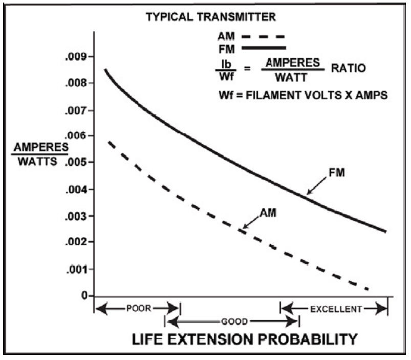
Figure 1. The probability of
extended life service can be determined from this graph. Divide the
average anode current in amperes by the product of filament voltage and
current. The resulting amperes/watt ratio is projected horizontally to
the appropriate curve. The vertical projection to the X-axis indicates
the life extension probability. |
First, Eimac warns us to never use minimum voltage life-extension on
heater-cathode type tubes. Reducing filament voltage on 8877 or 3CX800A7 tubes
(and similar) is a sure way to ruin tubes quickly.
Notice Eimac’s text applies ONLY to AM and FM broadcast. There
are important differences between broadcast and amateur use.
Why does Eimac use average current and filament power
to determine probability of successful life increase with filament
voltage management?
Current indicated on amplifier
meters is generally plate current and grid current(s). These currents
are the average currents, not only over longer periods of time, but also
over each RF cycle. Instantaneous peak cathode current in a small tube
like a 3-500Z might be as high as several amperes while we see only 400
mA plate current and 125 mA grid current on front panel meters (525 mA
average cathode current).
The filament-cathode must comfortably supply the instantaneous
current, or internal current waveform will change from emission
saturation causing peak clipping during each plate current conduction
cycle. Peak currents can significantly saturate even if average currents
barely change, and remember instantaneous peak grid current adds to
anode current demand from the cathode.
Peak emission current, in a properly designed and constructed
filament, is tied to filament power for that particular construction.
Eimac carefully optimizes filament emission for a given filament power
(heat), giving them a good idea how much instantaneous peak current an
emitter can supply for a given filament power.
Proper operation depends on instantaneous peak current,
but we cannot directly measure that current in an amplifier. We can,
however, measure the effects of not meeting peak current. Those effects
would be increased intermodulation distortion when amplifying
multiple-tone signals, increased distortion when amplitude modulating a
stage, or a decrease in power with a steady carrier.
Since SSB or AM has a much higher ratio of instantaneous peak to
average current than CW or FM, we need much more emission for a given
average current.
This is why Eimac tells us to measure distortion on amplitude
modulation and power on FM, and that we must watch for changes as
filament voltage is reduced.
|
Minimum filament voltage is determined by peak emission currents demanded
from the tube. If we set filament voltage too low for the required peak current,
we can shorten tube life. If we are on SSB or modes producing multiple
frequencies at the same time, intermodulation products (splatter) and distortion
will greatly increase. Eimac warns reduced voltage must be accompanied through
performance verification.
Looking at the above graph for a 3-500Z, we would find an anode current to
filament power ratio of .4/75 = .0053. That would work for CW or RTTY by using
the FM curve, a steady carrier. There is an excellent chance of tube life
increase for a near-continuously operated high-quality 3-500Z tube on steady
carrier, or off-on keyed modes. The best candidates for increased life though
minimal filament voltage are obviously conservatively operated FM or CW
transmitters. The least likely to succeed, amateur SSB transmitters running near
full tube ratings.
For SSB, let’s just use an average current of .3 amperes.
0.3 / 75 = .004. The AM curve predicts a poor chance of life extension through
voltage reduction, SSB logically should similarly less successful. Meeting peak
SSB emission current requirements (to minimize splatter) prevents significant
filament power reduction unless output power is also reduced. Most amateurs are
unwilling to give up 25% of output power to have a tube potentially last 50%
longer in emission, especially when it is very unlikely they will ever have a
filament-hour emission related failure.
Since Eimac does not give SSB data, I cannot be sure how AM stacks up with
SSB. Anything I say about this is a bit of a guess. VK1OD suggests about .007 as
the correct number, while I am at about .004.
Looking at the 811A or 572B tube, we find a SSB life extension probability
somewhere around .10/25 = .004. Once again we have a low probability of
successfully extending tube life though filament voltage reduction below normal
specified filament voltage ranges, unless we greatly reduce power. This also, of
course, considers the primary failure mechanism depletion of the filament
emission over a very long time of steady operation, and not other failures like
poor quality or mistuning.
In the real world anything we do to the filament, besides something really
bad like excessively low voltage or going over 120%, isn’t very likely to change
our tube’s lifespan, because amateur radio tubes almost never fail from emission
depletion. As a matter of fact the only tube’s I seen fail from filament voltage
have been oxide cathode tubes operated at excessively low voltage. Most directly
heated ham tubes fail because the operator is heavy handed when tuning, or the
tube is just a bad tube.
CPI/Eimac’s filament management program adds the following
requirements (directly quoted):
Instrumentation
Are all tube elements metered in the transmitter?
Elements should be metered for both voltage and current, and meters
should be red-lined to define operation within safe limits. Modern
transmitters may incorporate a microprocessor controlled circuit to
monitor all pertinent parameters. In addition, the following controls
are necessary if effective filament voltage management is to be
undertaken:
Power output metering for an FM transmitter or a distortion level
meter for AM equipment
Accurate filament voltage metering; an iron-vane instrument
is preferred over the more common average responding RMS calibrated type
but true-RMS digital meters are acceptable.
The filament voltage measurement must be made at the tube socket
terminals and filament voltage control should be capable of being
adjusted in 0.1 V increments.
|
From Eimac’s filament management program, we
see any reduction to minimal filament voltage must be accompanied with the
following:
-
Voltage must be accurately measured,
monitored, and “red lined” with proper instrumentation, not common meters
-
Power output must be monitored on FM,
and distortion
monitored with amplitude modulation. This would also apply to SSB
-
Filament voltage must be stable and
adjustable, so it can be set at the proper operating point without causing
distortion (splatter)
Unfortunately, many amateurs have been
misled by a few who have misread, omitted data from, misinterpreted, or
misquoted Eimac’s filament management programs. Amateur equipment and amateur
use often falls well outside Eimac’s filament management program guidelines.
If we actually read and follow Eimac’s
filament management, we will find the following data. Please pay special
attention to the “stars” below, and to what Eimac tells us:
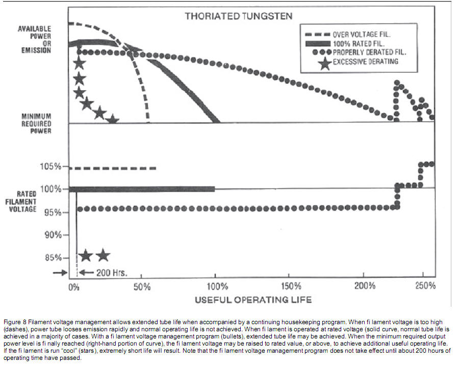
Notice if we set voltage too low, emission
life can be as short as 20% of normal. The shortest life curve above is from
excessively low filament voltage.
Have you ever saw an article warning about
low filament voltage?
Procedures in CPI Eimac and Econco
Filament Voltage Adjustment
No amateur can or will follow Eimac’s
procedure properly. Every instruction I have found, from AG6K’s website to the
recent QST article, is both improper and greatly over optimistic. Everything I
have found instructs setting voltage at minimum allowed voltage
without testing intermodulation to confirm adequate reserve emission. Nowhere
(except in Eimac’s article and here) are consumers warned against excessively
low voltage.
If filament voltage is set too low, two
potential problems appear:
1.) Intermodulation or splatter increases
2.) Filament life can be greatly shortened,
actually more than any other error
Here is Eimac’s actual procedure for
adjusting voltage:
When a noticeable change occurs in the output
power or if the distortion level changes, the derating procedure must
stop. Obviously, operation at and beyond this point is unwise since
there is no margin allowed for a drop in line voltage. The voltage
should be raised 0.2V above the critical voltage at which changes are
observed to occur. Finally, recheck power output or distortion to see if
they are acceptable at the chosen filament voltage level. Recheck again
after 24 hours to determine if emission is stable and that the desired
performance is maintained. If performance is not repeatable, the
derating procedure must be repeated. Continuing the Program The filament
voltage should be held at the properly de-rated level as long as minimum
power or maximum distortion requirements are met. Filament voltage can
be raised to reestablish minimum requirements as necessary. This
procedure will yield results similar to those shown in the illustration
(Figure 8), to achieve as much as 10% to 15% additional life extension.
When it becomes necessary to start increasing the filament voltage in
order to maintain the same power output, it is time to order a new tube.
Filament voltage can be increased as long as the increase results in
maintaining minimum level requirements. However, when a voltage increase
fails to result in meeting output level requirements, filament emission
must be considered inadequate and the tube should be replaced. Dont
discard it or sell it for scrap! Put it on the shelf and save it. It
will serve as a good emergency spare and may come in handy some day.
Also, in AM transmitters, a low-emission RF amplifier tube can be
shifted to modulator use where the peak filament emission requirement is
not as severe. |
Eimac’s text above obviously requires us to have a periodic schedule of
measuring distortion, to keep emission safely above minimum levels. At the time
of this writing, I have not found a single amateur article that comes close to
proper instructions.
Applying Eimac’s Filament Management
Program to Amateur Use
Eimac’s filament management program applies
to commercial transmitters operating with long uninterrupted filament hours,
almost always with greatly reduced RF power levels. Extension of operating hours
through use of minimal filament voltage works under the following conditions:
-
The tube is properly
manufactured, and has survived normal infant mortality periods where
tube manufacturing defects primarily appear
-
The filament is not cycled
frequently relative to operating days
-
Other tube parameters, such as
seal temperatures and element heat limits, are not exceeded
-
Filament voltage is stable, and
either monitored or regulated, and minimum voltage is set at times
of minimum line voltage
-
The filament power to average
emission current meets certain ratios for certain modes. This ties
back to peak emission current
-
Operation is at a consistent or
predictable absolute maximum power level, and proper operation at
reduced voltage has been verified
-
The tube is a directly heated
thoriated tungsten emitter, and does not employ a metal oxide
cathode tube (i.e. 3CX800A7 or 3CX1500A7)
-
We periodically verify
distortion on SSB, or minimal emission levels on CW, for the band
that has highest peak cathode current when line voltage is minimum
-
We continue to verify and
readjust voltage throughout tube life
|
Without question, all indirectly heated
tubes, low quality tubes, and nearly all amateur equipment falls well outside
Eimac’s guidelines for extending tube life through use of minimal filament
voltage. Not only is the equipment used differently and without regulated or
controlled filament supplies, virtually no one can or will periodically measure
intermodulation to confirm proper operation.
So what does Eimac say, when we cannot meet
the above requirements? Here is another unedited quote from Eimac’s filament
management programs on extending tube life:
|
NOTE: If the filament voltage cannot be
regulated to within ± 3%, the filament should always be operated at the
rated nominal voltage specified on the data sheet.
It should be noted that there is a
danger to operating the emitter too much on the cold temperature side.
It may become poisoned. A cold filament acts as a getter; that is, it
attracts contaminants. When a contaminant becomes attached to the
surface of the emitter, the affected area of the emitter is rendered
inactive, causing loss of emission.
|
If we cannot regulate the filament, Eimac tells
us to run the tube
centered on the nominal voltage specified for the tube. Of course
we should avoid going outside tube or equipment manufacturer filament voltage
limits. Since going below low limit (see graph above) causes shortest life, and
since no amateur is going to measure distortion, I set the filament voltage
within allowable
upper tube filament limits at the very highest line voltage.
A little known or understood fact is I test my
amplifier designs extensively over expected line voltage variations for
distortion and general performance. Also, if designs go outside ratings, I
consult with actual tube design engineers responsible for the tube design. This
was done with the 3-500Z back in the 1980’s, when Salt Lake produced glass power
grid tubes. Everything in the manual regarding tube operation was “bounced off”
the proper Eimac tube design engineer, and approved.
In a 3-500Z nominal voltage is 5.0 volts, with
recommended a range between 4.75 and 5.25 volts. The design does not allow for
operation at voltages below 4.75 volts, yet that is where QST has readers set
voltage in a recent article. QST was not responsible enough to check with the
designer, read filament management programs, or check with the equipment
manufacturer before publishing their article! All information was available, it
is not new.
The AL80B, along with all other Ameritron
products, have been carefully engineered to not exceed rated filament voltages
when the appropriate line voltage tap is used. While it is
possible to recover a thoriated tungsten emitter that has been poisoned
through low voltage operation, an oxide cathode that has been damaged from low
temperature operation is generally not recoverable.
How Do We Set Optimum Tube
Filament Voltage?
Incorrect filament voltage,
either high or low, reduces filament emission life. The worse condition is
excessively low voltage. Other than low voltage induced failures of metal oxide
cathodes that can happen in minutes or hours, very few of us will ever
experience time-depleted emission in a large transmitting tube. We may witness
common emission loss in poorly manufactured import tubes, and on rare occasions
even Eimac has a bad batch in their high quality tubes, but few will ever run
their tube’s emission out through normal amateur filament hours. This is true
even when filament voltage is 10% or more high, as we see in older Dentron
amplifiers. Still, we should adjust filament voltage properly for our
application.
Low Voltage
Excessively low filament voltage
causes insufficient cathode emission. This creates three common problems:
1.) loss of linearity during
peaks, causing splatter
2.) greatly accelerated emission
loss from filament poisoning. This is a more rapid failure than excessive
voltage can cause
3.) limited power output
(premature cathode current saturation) and/or reduced plate efficiency
Eimac tells us, as do vacuum tube
engineering books, we should never run minimal voltage or reduced voltage on a
metal oxide cathode tube. Always set a metal oxide cathode tube so minimum
filament voltage, at the lowest point in mains voltage, is above the minimum
voltage specified by the manufacturer’s data sheet.
Directly heated thoriated
tungsten filaments can have voltage reduced, but only if we are willing to
measure distortion and closely monitor and regulate filament voltage. Very few
amateurs will go through such trouble, especially since hours are so low, import
tube quality so low, and other stresses so high that virtually no failures come
from filament-hour emission loss.
Proper Procedure
First, we must have a good meter.
Anyone using an unverified 2% average reading AC meter to fine tune voltage is
just deluding himself. We must also measure filament voltage properly at either
the time for highest line voltage or time of lowest line voltage, or apply a
correction to voltage based on known variations and line voltage at the filament
measurement’s time.
If filament voltage is too high
or low, and we want to optimize filament voltage, we must first make sure the
amplifier power mains supply is as stiff as possible. This would include
shifting high current loads to 240-volt circuits, and running the largest size
wire practical from mains to the amplifier.
After we are sure the mains are
as good as reasonably possible, we have to learn our mains voltage variations.
This will include spending some time monitoring or periodically measuring line
voltage, in particular at primary operating times.
Once we learn the line voltage
range and ratio of line voltage to filament voltage on tube pins,
we can make adjustments.
The easiest, fastest, and most
reliable way to adjust filament voltage is by finding the very highest line
voltage ever expected in normal operating times, and adjusting the filament
voltage just below the data sheets safe upper operating range limit. This
ensures the tube is unlikely to ever go outside a safe limit, and has the most
headroom for sag caused by power line loading, transformer heat, and other
voltage reducing effects. Unless your amplifier accumulates very uncommon hours
of operation, this all you need to do.
If your amplifier has extreme
filament hours, perhaps averaging 8 hours daily or more on average, and
especially if you run it well below maximum power, you may want to aim for the
lowest and highest voltages centered on the nominal data sheet voltage.
Personally, I would never bother with this.
QST’s October 2011 ” The Care and Feeding of a
3-500ZG Amplifier “
article comment
link
Repeatedly the Ameritron manual warns users
always disconnect the amplifier from power mains before removing
the cover. Repeatedly, the manual warns customers
never to defeat the interlock. Repeatedly, the manual
warns customers never to power up the amplifier with the
cover removed. |
In the AL80B, the following measurements occur:
|
Using AL80B instruction manual
125-volt maximum line settings
|
|
Line voltage
|
Article test point
|
Filament pin voltage (cold)
|
Filament pin voltage (hot)
|
|
124.1
|
5.32
|
5.21
|
5.15
|
At maximum line voltage for the AL80B’s Instruction Manual
tap setting, with a warm amplifier, filament voltage is 5.15 volts. This is well
within the tube manufacturers allowable range of 4.75 to 5.25 volts
|
245-volt maximum voltage settings with a cold amplifier |
|
Line voltage
|
Article test point
|
Filament pin (cold)
|
|
246.2
|
5.36
|
5.25
|
Again, the AL80B is within specification when the proper
power transformer taps are selected. In the AL80B, measure power line voltage
over time. Wire the transformer for the maximum expected line voltage.
I specified setting voltage in Ameritron amplifiers for the
highest possible line voltage. The ideal minimum from that voltage would be
about 8% less. This means the 125 volt tap keeps the filament in range from 115
to 125 volts. Setting for maximum line voltage does two things:
-
Filament voltage stays below recommended maximum values
-
Filament voltage will not go below the measured value
where typical 3-500Z’s deteriorate in intermodulation performance
The normal filament voltage range for a 3-500Z tube is
given in widely available data sheets. The documented filament voltage range is
4.75 to 5.25 volts, not some voltage invented by random people.
AL80B Filament Voltage Compensation
When I design shared filament/HV transformer
systems, I include special transformer design considerations. I consult with
some of the best transformer design engineers available, and one of the best was
Ernie Smith from Schumacher Electric. Ernie and I worked to constantly improve
transformer designs.
The AL80B, like most amplifiers I design,
uses optimum internal placement of windings, core size, and primary design. The
design focuses on the filament system, where filament center tap voltage balance
and filament voltage stability with transformer load variations is paramount.
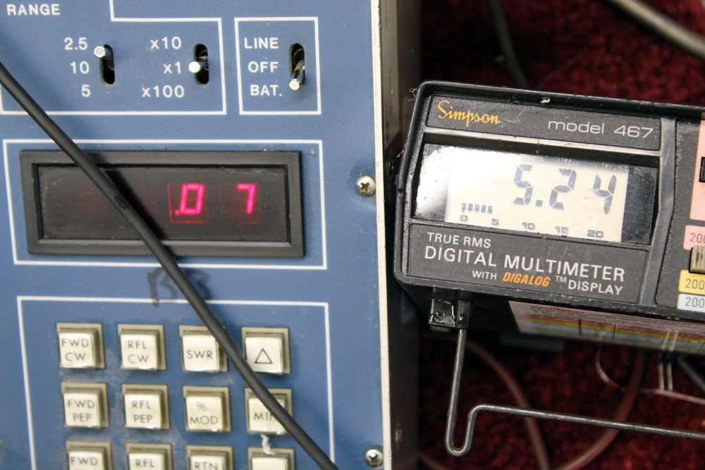
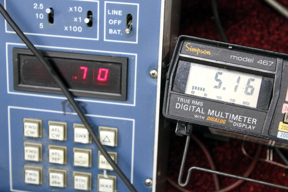
The AL80B is remarkable for a single
transformer design. With a reasonably good power line, AL80B filament voltage
typically changes less than 2% from no load to 1.3 kilowatts DC load on the
power supply. For example, using my 124.5-volt line (at that moment) and the
125-volt maximum voltage transformer taps, I measured a filament voltage change
on a typical digital meter from 5.24 volts no load to 5.16 volts with 1.35
kilowatts DC load on the 3-500Z filament/plate transformer. A taught-band meter,
generally better for RMS voltage measurements, shows no filament voltage
movement at all. We can be reasonably sure filament heat changes less than 2%
from no-load to full-load in the AL80B if power mains are reasonably good.
This is exceptionally good regulation for a
combination filament/high voltage transformer. This system had hundreds of hours
of careful thought and measurement.
Correct Filament Measurement Methods
It is actually not necessary to measure
filament voltage in Ameritron amplifiers. That work has already been done for
customers. All you really need to know is your outlet’s highest line voltage.
You simply look in the manual, and select transformer primary wiring closest to
but still above the highest line voltage. That completes the job. With 14
voltages available, there is little reason to cobble up the amplifier by adding
a coil of hookup wire (that also unbalances the transformer center tap).
The procedure below can be used in other
systems to measure filament voltage. It is not for unskilled people, and you
should always consult the manufacturer of your equipment whenever possible
before making any changes. The intention below is a demonstration of proper
measurement techniques. They do not necessarily apply to other systems.
While measuring AL80B filament voltage is
generally unnecessary, a relatively safe method would be:
- Unplug the amplifier
- Verify zero volts on the HV meter
- remove the cover
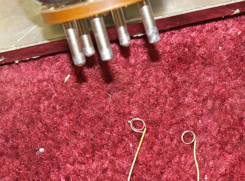
Using very small Teflon or high temperature insulation
wire-wrap wire, pre-form the ends to be tight around tube pins
Make sure pins are clean, but do not scrape plating off
pins or solder to pins
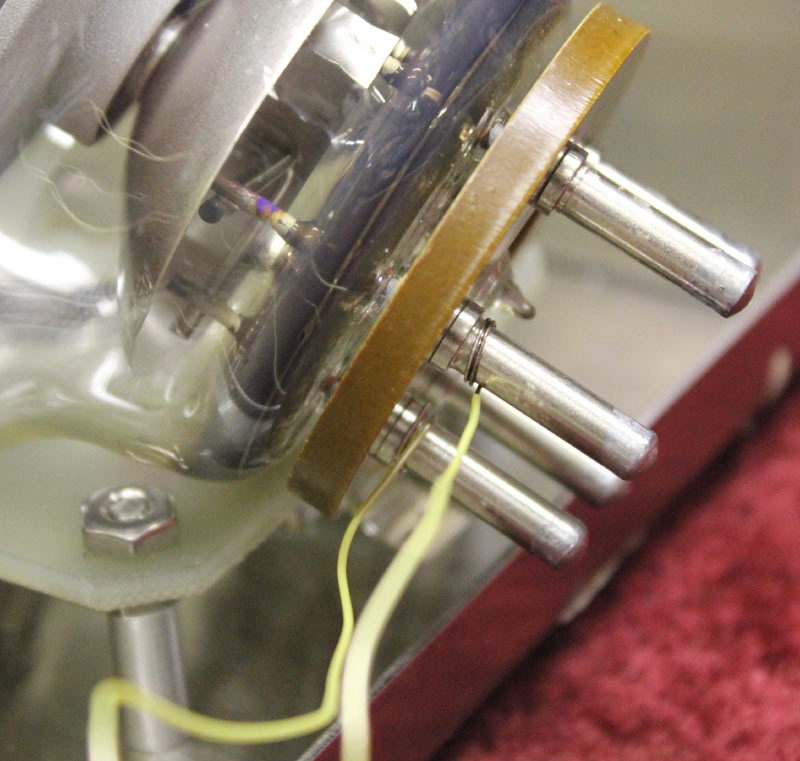
Slide wires over the filament pins. They should firmly fit
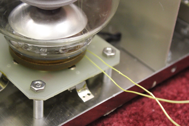
With tube in socket, wires exit like this
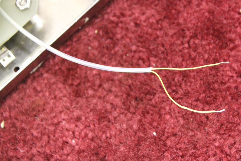
Sleeve the wires with an additional protective sleeve
This prevents damage or shorts when cover is installed
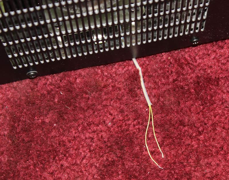
To confirm connections, measure wire to wire resistance
while wiggling wires
Resistance should be low and remain low compared to meter
input impedance
Reinstall cover and replace screws
Do not over-tighten and crush test wires
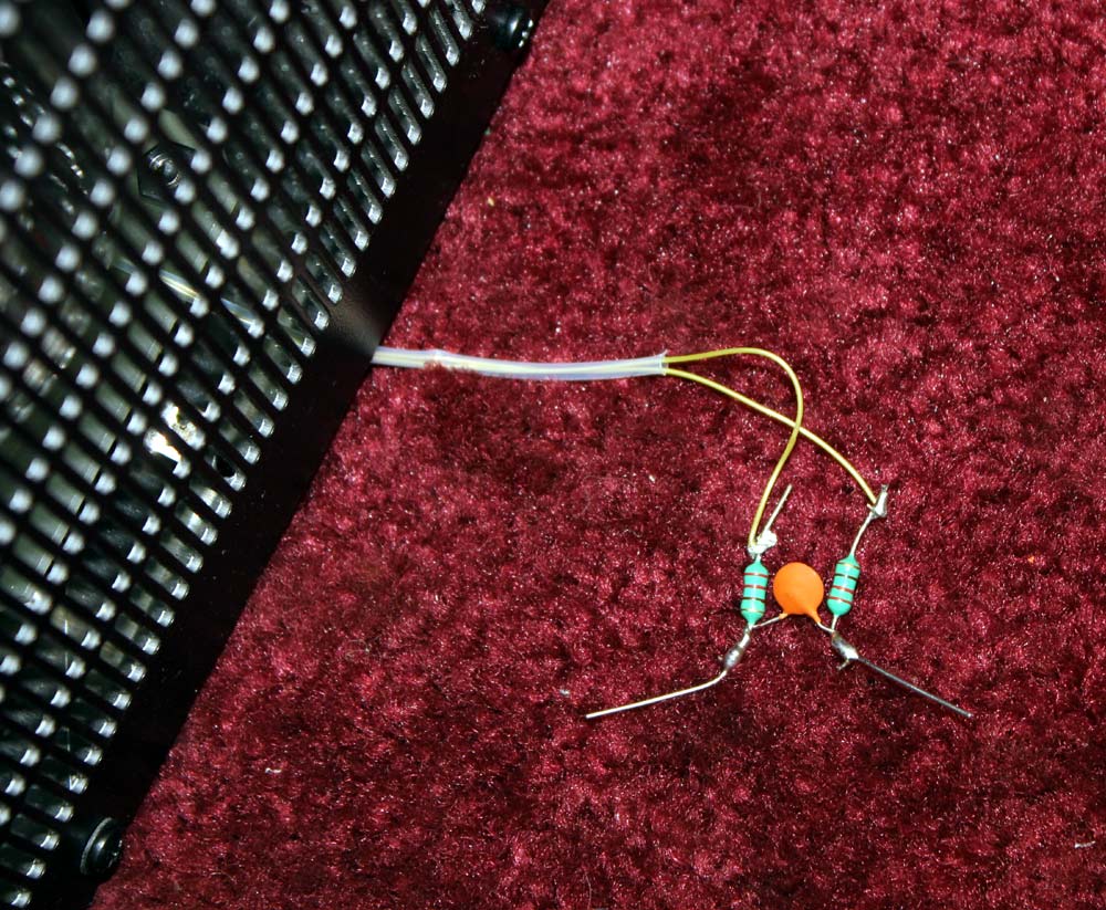
Install an RF and transient filter
Series components are 220 µH
RF chokes
Shunt component is .1 µF
capacitor
- Connect the filament meter across the capacitor
- Use either an accurate analog AC RMS meter, or a true-RMS digital meter
- Most digital meters are average-reading types calibrated in RMS
- Connect the amplifier to the mains. Meter wiring must not be touched
beyond this point; filament voltage can rise to several hundred volts if a
tube arcs
- Turn on power
- High voltage should come up around 3000 volts
- This is the voltage that will kill when amplifier cover is removed
- Never power the amplifier up without a cover
- Never defeat the interlock
- Measure filament voltage on a TRUE-RMS meter with no load at your
highest line voltage
- I use a verified calibration meter, since most meters are 1-2% tolerance
In this case on the 125-volt transformer setting, with 124.5-volts on my
power line,
filament voltage was 5.24 volts no load
this was with a cold amplifier, voltage will decrease about 1% at operating
temperature
- be sure filament voltage is measured or noted
- it can be adjusted to correct for line voltage range at your location
- voltage should close to but under 5.25 volts as possible at your
maximum
line voltage
- this assures the tube does not “splatter” on SSB
- when line voltages are low or when the tube ages, and that
- filament voltage never goes over the maximum filament voltage
recommended
If your power line voltage sags more than ~10% during certain times of the
day, in particular if your tube is a little low on emission, there may be a
slight increase in intermodulation products (splatter). This can be avoided by
running about 20% less peak power when line voltage is more than 10% below
maximum setting.
Summary
Information regarding tube life and filament voltage in amateur publications
is sometimes nether safe nor reliable. Measurement methods are generally wrong,
target filament voltage are often wrong, and life change predictions are almost
always grossly exaggerated. Measuring pin voltage is sometimes not even
necessary if instruction manuals are followed and maximum power mains voltage is
known. For example, the AL80B has fourteen
different line voltage settings available. Ameritron amplifiers built after
1990, and most Ameritron amplifiers manufactured before 1990, have multiple
voltage taps for filament adjustment. Do not reduce filament
voltage by adding resistors or extra filament wire length. Measure your actual
maximum line voltage and wire transformer taps according to the
instruction manual.
- Adding wire or resistance to one side of the filament path is also not
advisable if filament voltage should ever be high.
- Reducing filament voltage to values suggested in some articles can
seriously shorten useful tube life, and increase signal bandwidth on SSB.
- Never connect an amplifier to mains with a cover removed, and never
defeat an interlock.
Watching tube failure problems constantly, most tube failures center around
operator error, poor tube manufacturing quality control, and poor manufacturing
and testing techniques at tube manufacturers. I don’t expect anyone to realize
an amateur service tube life increase by reducing filament voltage. Eimac’s
Filament Management Program shows a “poor” life extension probability from
filament management in amateur-type applications. I agree, especially in light
of the fact no one is going to constantly monitor distortion, filament voltage,
or anything else.
Link to
QST Article
copyright 2011 W8JI
|