Blocking Capacitor
|
|
|
Many people needless oversize the blocking capacitor. This doesn’t mean you
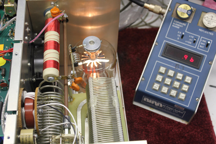
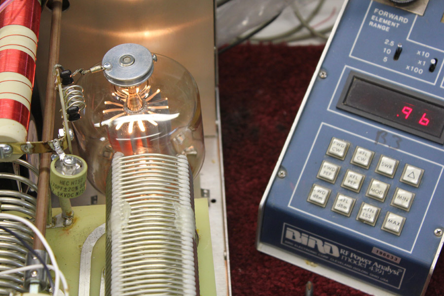
The 2000 pF capacitor outputs 960 watts PEP with an old Chinese 3-500Z tube
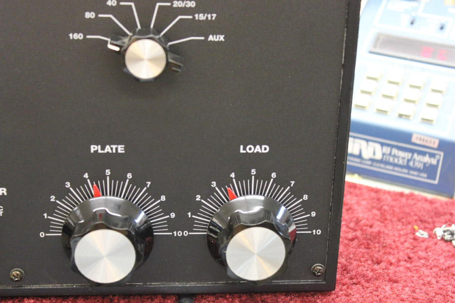
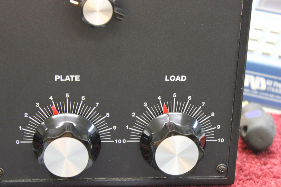
The front panel knobs are at this position:
Plate is at 4-1/4 Load is at 3-1/2
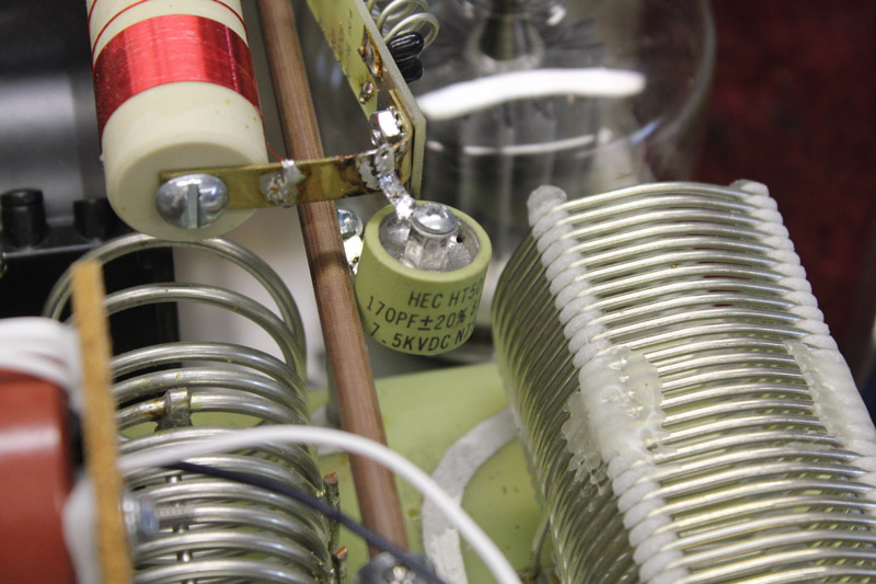
A 170 pF is substituted for the 2000 pF.
This is a quick test with only the blocking capacitor changed.
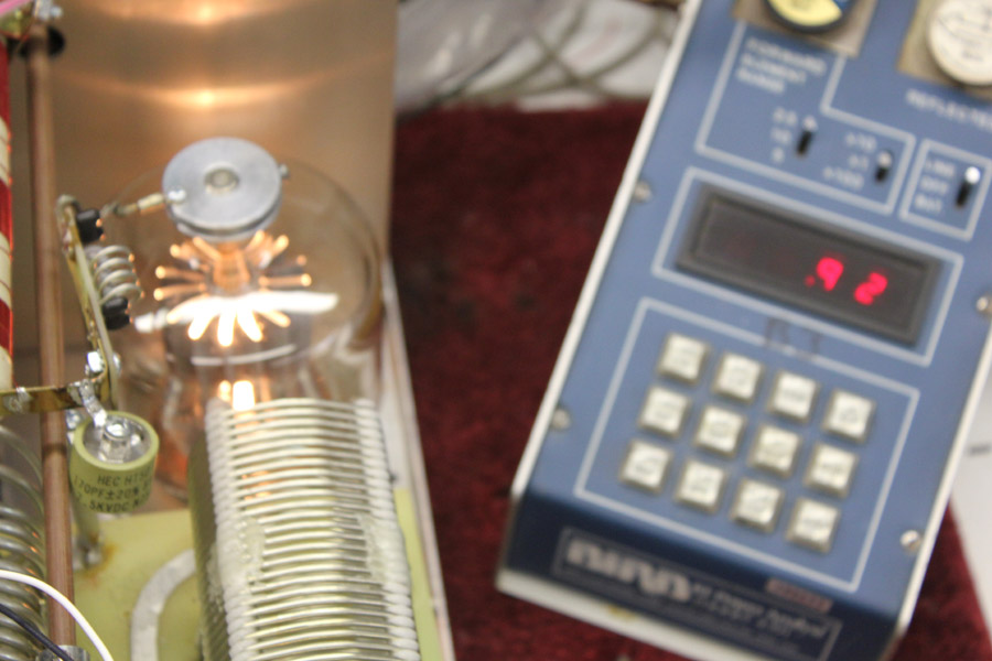
Power, not retuned, is 920 watts PEP. This is a 2% drop in power.
Retuned power:
Retuning the Plate and Load brings power back to 960 watts PEP. No power
The new settings are
Plate 4 Load 4-1/4 Old settings were
Plate is at 4-1/4 Load is at 3-1/2 The only effect is a slight change in control settings, just a few percent.
Note: This does not mean you should change parts to new values. It simply is Efficiency is determined by conduction angle and waveform at the tube anode,
Blocking Capacitor Current
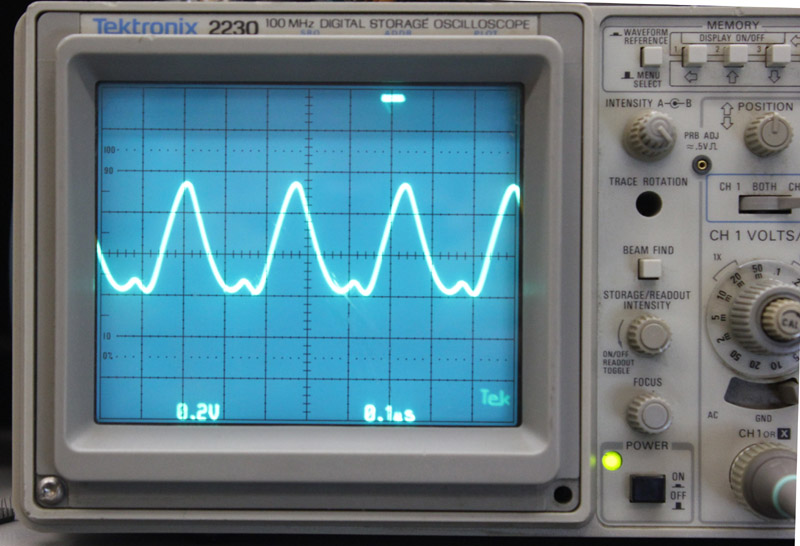
This is the blocking capacitor current in an AL80B amplifier running 850 Note the current is not symmetrical, peaking at ~1.275 amperes. The positive This waveform gradually varies from band-to-band, but is never symmetrical. This waveform is representative of the 160-20 meter blocking capacitor The sine shaped part of the curve is during the period where the tube With peak current ~1.275 amperes, peak capacitor RF voltage drop would be
© 2011 w8ji
|
