AL811 series install TOF and TOF with Grid Protect
Most amplifiers require a special TOF module. The wire colors
and resistor values are different. Be sure you have the correct TOF module.
Limited sales volume have
made this impossible to produce. This is no longer available.
LED Warning Indicator
The LED warns by brightly illuminating when exceeding the typical
maximum peak grid current for proper linear amplification. The LED system
indicates occasional over-current much better than the panel meter. If you open
the LOAD control (clockwise) and the LED does not go back to occasional sharp
quick flashes (from occasional ALC overshoot or strong peaks), or does not stay completely off, the amplifier is
likely being
overdriven. Reduce the drive power until the LED just flashes occasionally, or
the LED stays completely off.
The warning LED may occasionally
flash on voice peaks from radio power overshoot. This is generally not harmful
or disruptive to others, or to the amplifier. If the LED illuminates longer than very brief flashes
or blinks, or illuminates with almost every word, the amplifier is being overdriven or
has been mistuned.
AL811 (3 tube) with LED being overdriven:
Installation TOF1 series in AL811 and AL811H
#1 and #2 Phillips
screwdrivers
Soldering equipment with small rosin flux solder,
preferably WRAP2 rating but any electronics solder will work
Drill for LED if you chose to install it
Included in kit:
TOF1 with precut wires
two small cable ties
LED tape
The amplifier must be tested and properly working before
installation.
1.) Disconnect the amplifier from the mains. Allow a safe
discharge time for capacitors, 10-15 minutes is more than ample.
2.) Check HV to be sure it is at zero volts.
3.) Remove cover
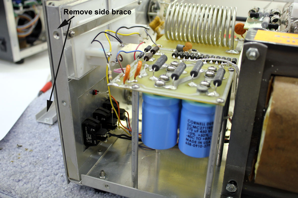
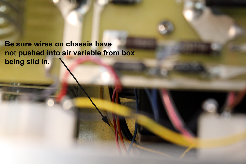
4.) Remove just ONE side brace as shown. Do NOT remove the
opposite side’s bracing. It is necessary to slightly bow the back and front to
remove the brace.
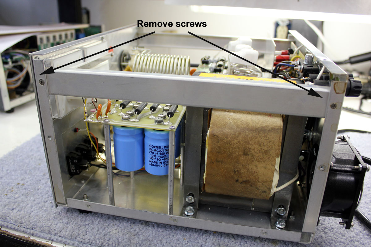
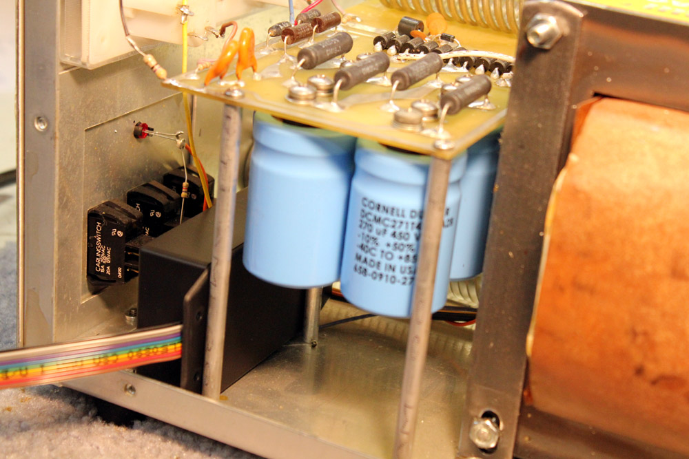
The amplifier should now look like this:
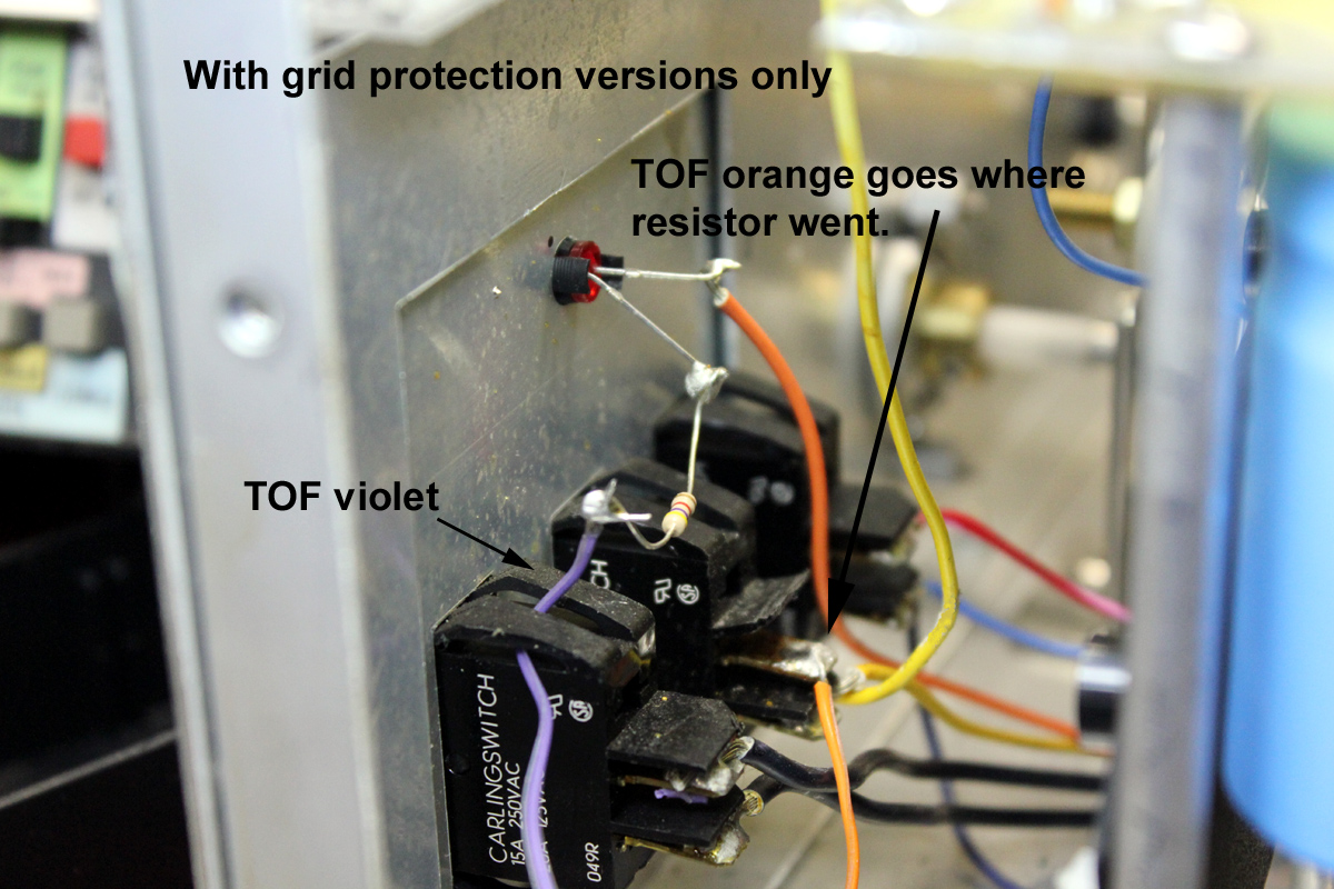
TOF with grid protect must have Orange and Violet wires
connected to standby and LED before mounting the TOF.
Loop the Violet wire through the power switch tabs to
support the Violet wire and resistor. You must separate the wires out of the
ribbon, as necessary, by pulling on the wires to split the wires apart in the
ribbon.
The picture below only applies to later 811’s with the
miniature rear circuit board relays. Early versions with an open frame relay
have the resistor soldered across the LED, but otherwise connect the same way.
Orange to the standby switch where the LED feed was attached, and Violet
connects to the LED lead that formerly went to the standby switch.
The standby switch resets the overloads by removing power
to the Orange. The relays are powered through the Violet wire.
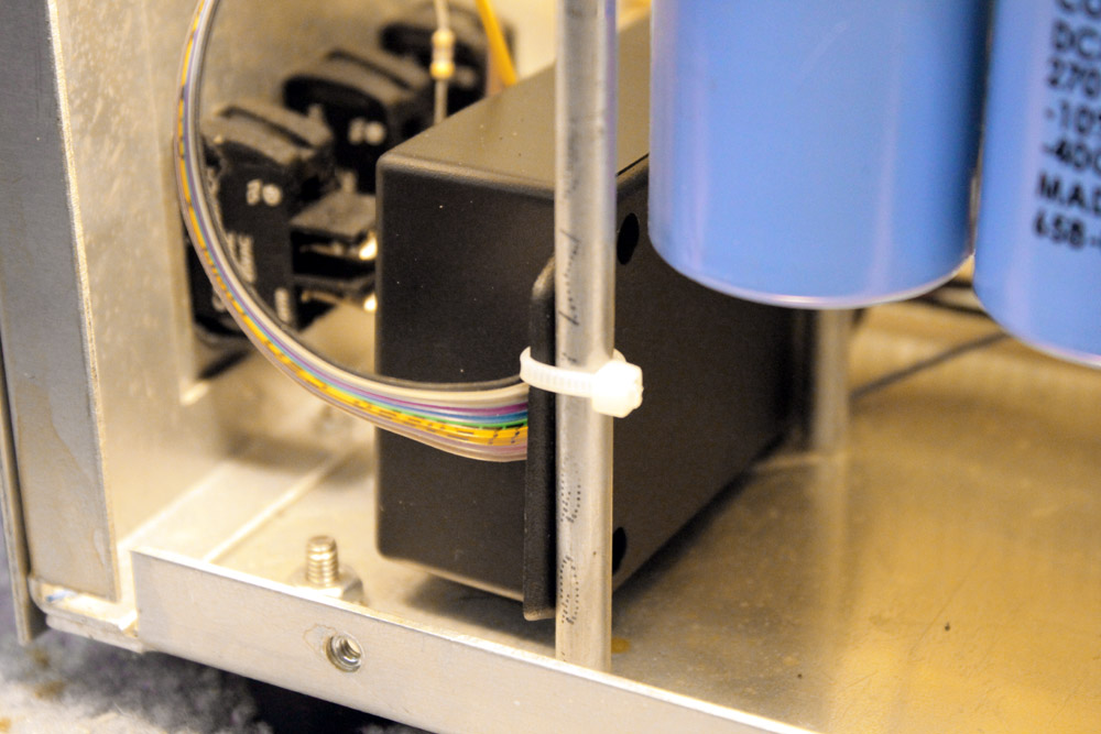
5.) Install the TOF1 as shown
6.) Tie wrap the TOF1 in place. The factory wiring will hold
the TOF inside in place away from the switches.
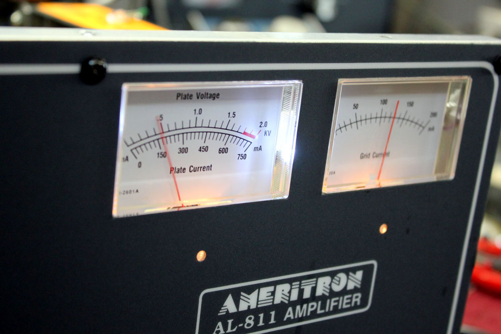
7.) The original meters and wiring will look like this.
Unsolder the blue wire from the grid meter:
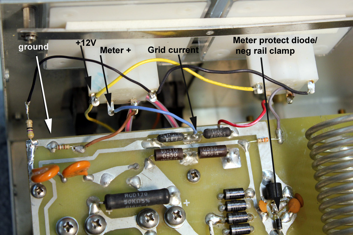
8.) Pre-tin any connection points with fresh solder. The FOUR
connection points are shown below, along with a diode that protects the meter.
The diode is shown for troubleshooting purposes:
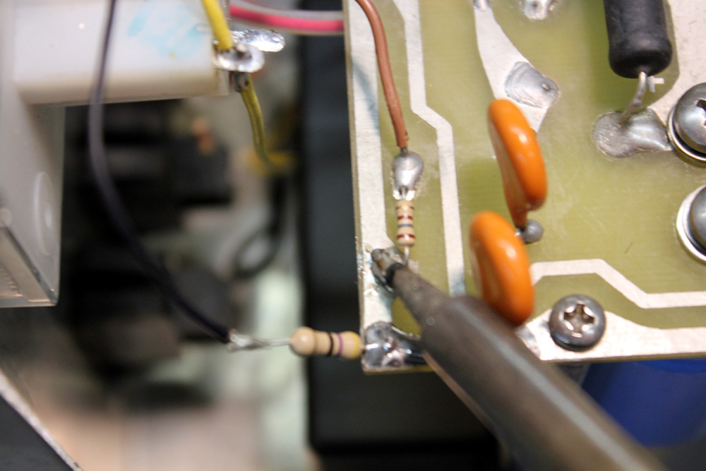
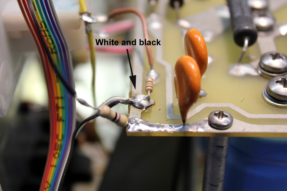
9.) Connect the wires as a shown below. First the black and
white wires. It is perfectly acceptable and I recommend laying the tinned wires
on the wetted pads of the board and sweat soldering them. Lead free solder
almost always looks a little like a cold solder connection. Just make sure you
have flowed the solder and the joint is mechanically sound:
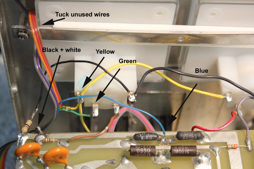
10.) Proceed to the other wires. You will have three yellow
wires on the meter lamp supply line, two original and one new wire. You will
also remove the original blue wire that connected between the two black meter
shunts:
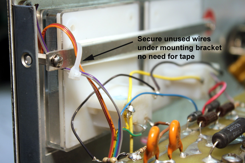
11.) Secure the unused wires with a tie-wrap. Check your wire
dress to be sure it does not get pinched by the cover or brace:
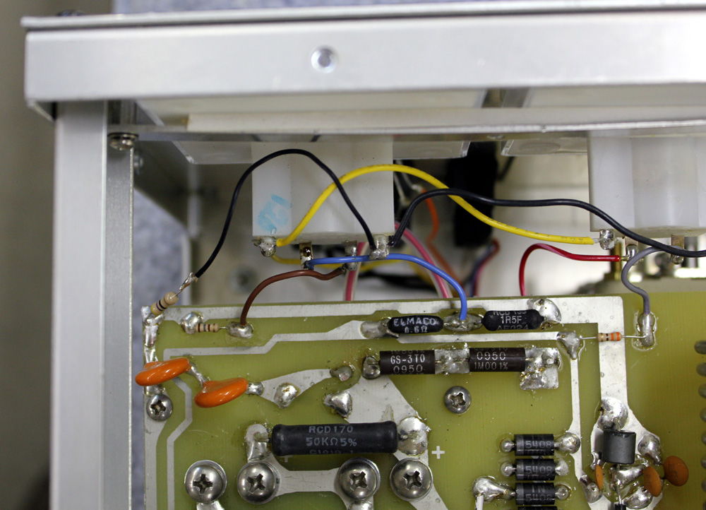
12.) After checking your work to be sure it matches the
picture below, replace the brace and cover:
Operation
After setting the amplifier for the band being used, adjust
your exciter to approximately 75 watts for the AL811 and 100 watts for the
AL811H. Speak into the microphone and adjust the TUNE or PLATE control for
maximum grid current. Be sure you have centered it on the peak.
While speaking in a normal voice, the LOAD control should be
adjusted for the currents shown below:
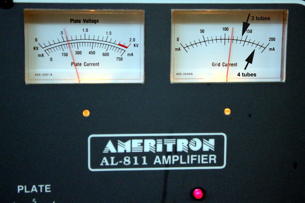
The meter should occasionally bounce over to the arrow marks.
If the meter pointer bounces past the arrow marks above, advance the LOAD. If it
never reaches those marks on peaks, move the LOAD counterclockwise.
The TUNE knob (PLATE) should always be set for maximum
possible grid current.
This adjustment procedure also works on CW.