AL811H Amplifier Myths, Changes, and Information
[ Home ]
Business Page Link
CTR Engineering, Inc
Also see:
AL811, AL811H,
AL572, other amps trouble shooting guide
811A Tube History
and Construction
Power Gain of AL811H Amplifier
The older AL811H (prior to drive resistor modification) with good
tubes and stable power line, when properly tuned and operating in the linear
region, has about 11 dB gain. This is an amplification of about twelve
times. With 60 watts of drive power, output is 720 watts. The power gain
is slightly higher on SSB than on carrier or high average power modes, but the
gain will be
reasonably close on
all bands. The largest single problem with significantly greater or less gain
(power output) is a poorly calibrated power meter. A mismatched antenna or load
can falsely increase power readings.
| Note: If you tune the amplifier at reduced drive power, gain increases. |
The following is typical measured gain of an early (pre-2011)
unmodified with good tubes
at 7 MHz with carrier power. Gain is slightly higher on SSB or low duty cycle,
because anode voltage is slightly higher. Units containing the shunt 200-ohm resistor require about 20% more
drive. HV is 1500 volts at full load:
| Drive watts
old style |
Drive watts
new style |
Power Output watts |
| 20 | 27 | 250 |
| 35 | 42 | 440 |
| 50 | 60 | 615 |
| 65 | 75 | 715 |
| 75 | 90 | 750 |
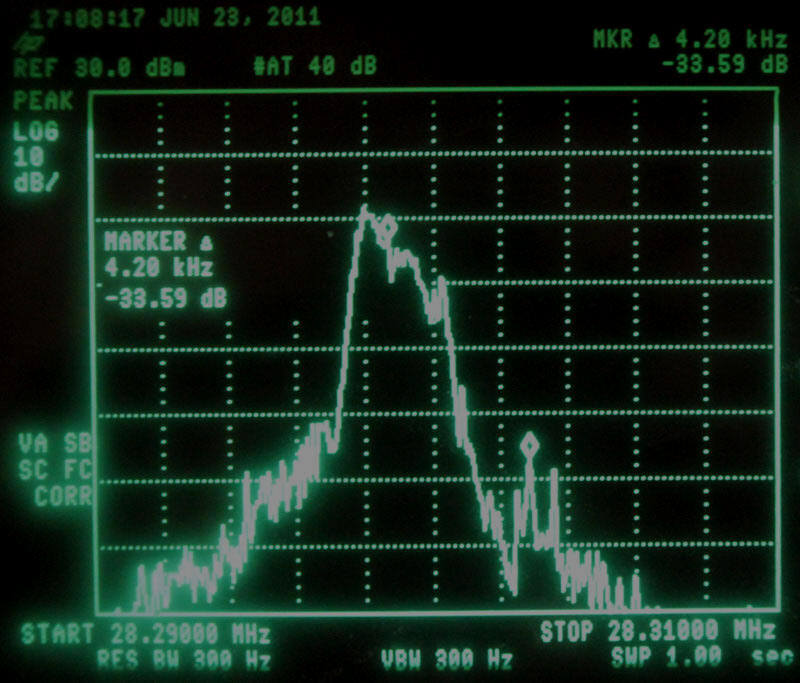
AL811H, highest peak power, in sidebands with normal voice
modulation at 700 watts PEP with fresh tubes on worse band, ten meters.
Next channel up, strongest peak is about -34 dB compared
directly to voice channel median power level.
LSB is about -32 dB, not much different than the barefoot
transmitter.
Properly tuned with good tubes, the AL811H adds
negligible bandwidth to a typical radio’s SSB signal, even on the worse-case
band.
This performance can be improved with a TOF
module.
Some AL-811 Myths on Internet
There is some history of the 811A tube at
this link.
A few common but false myths are:
811 tubes are critical for grid current
Factually, the largest number of field failures are damage to
anodes from excessive anode heating and low filament emission from poor tube
manufacturing quality. Grid related failures
are nearly non-existent. The most common cause of operational or customer
induced tube failure is excessive anode
dissipation over time. Heat is a function of duty cycle and short term average
dissipation. The 30-second or longer time-period dissipation (dissipation
is not the same as output power) must be kept below 60 watts. For short
periods (IVS service) dissipation can be much higher.
Life of 811 tubes will be extended by less anode voltage
Anode voltage, within reasonable limits, has nothing to do with
tube life or tube arcing. Virtually no tube failures relate to anode voltage.
Life of 811 tubes are extended by more airflow
811 tubes are designed to be natural convection cooled. Anodes,
which produce most of the heat, and the other heat sources are inside a sealed
glass envelope in a vacuum. There is very little heat conduction to the
envelope. The vast majority of heat is removed via infrared radiation and
radiated to tube surroundings. The only thing the air does is cool the glass
enough to prevent damage to seals or the glass envelope itself. External airflow
does not measurably improve anode cooling, and anode temperature is the limiting
parameter. See his link…airflow temperature
measurements
The 811H pushes tubes far beyond ratings
Absolutely true, if you consider operation in ICAS
or CCS and not IVS (intermittent voice service). Keep in mind however the 811H does not “push”
the tubes any “harder” than Collins did in the 30L1, or Heath did in the
Warrior. It has been a long standing tradition to run 811 tubes at about 250
watts dc plate input, which is about 150-175 watts RF on the anode, per tube.
This is why the Collins 30L1 was marketed as a “kilowatt” amplifier,
which is
over 600 watts output carrier.
The problem is not exceeding the 65-watt
dissipation for short periods, the problem is exceeding it with enough duty
cycle to overheat the anode. The most common problem today by far, excluding operator error,
is quality and design of tubes. Please read about
how the 811 tube got better, and then worse, with design evolutions.
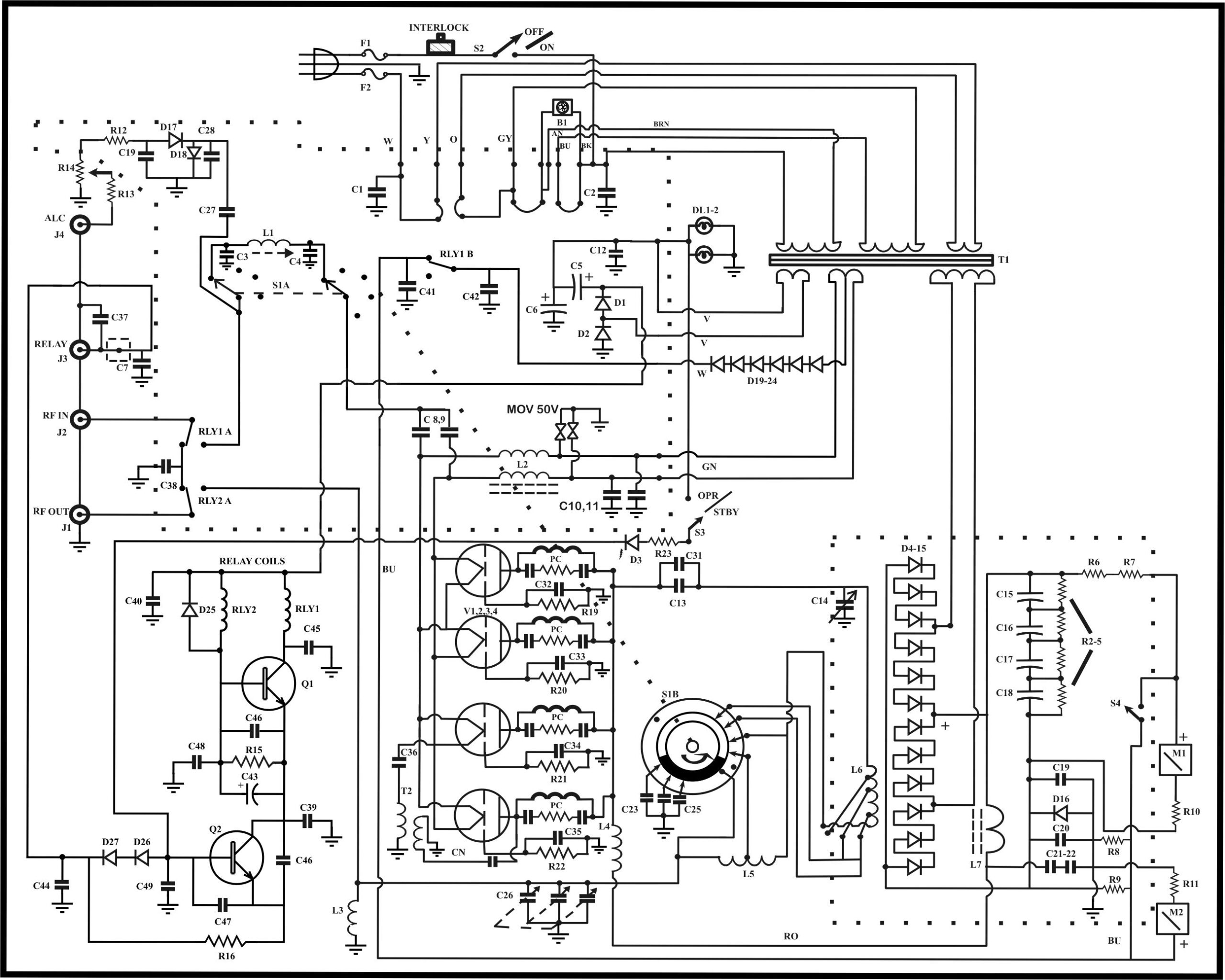
Below, hand drawn schematic early AL811H
New metering schematic:
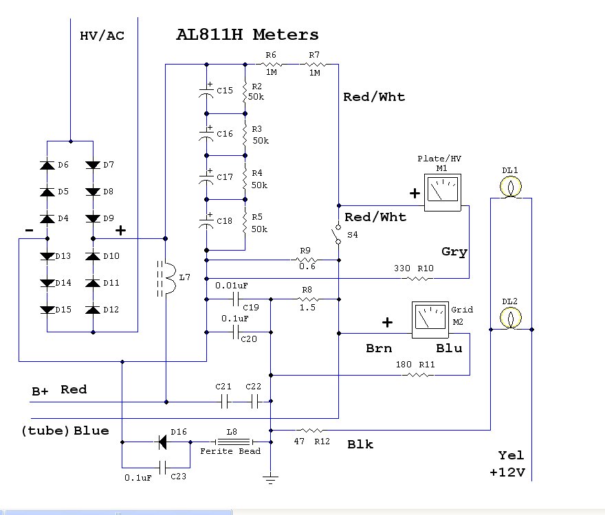
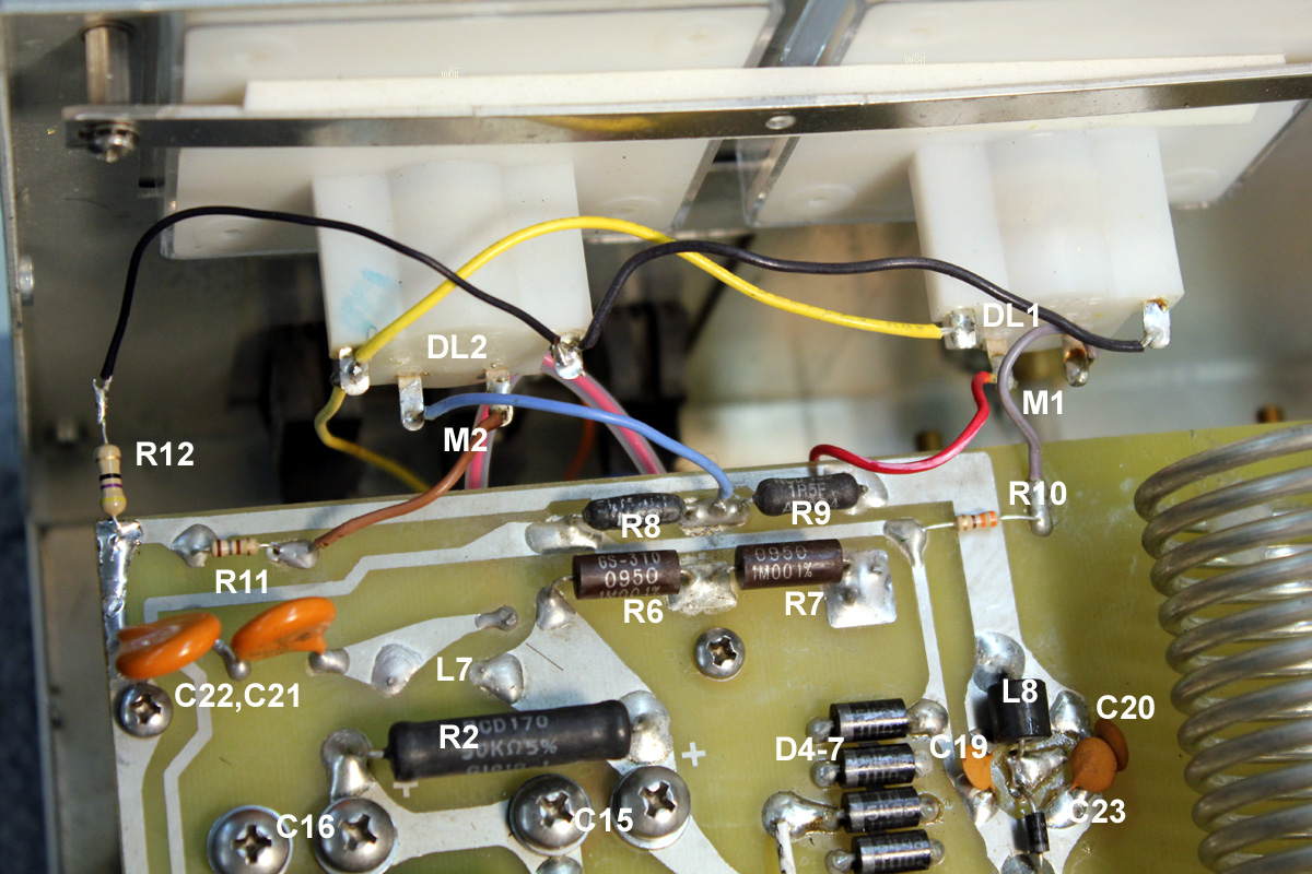
Meter protection diode D16 is the unlabeled small black diode
near C23. It protects the meters in the event of an arc. If D16 fails from an
arc, the grid and plate current meters will track. The grid meter will no longer
read grid current and the plate current meter will no longer read plate current.
They each will read a combination of plate and grid currents. This diode can be
replaced with any 1 to 5 amp silicon power rectifier diode that physically fits.
Design History
I designed the AL811 series amplifiers in the late 1980’s or early 1990’s. The
original concept by marketing was a cheap, two-tube amplifier, but I convinced
marketing that the life of two tubes would be far too short. I talked them into
a bare bones minimum three tube amp, and a slightly more refined four-tube amp.
Amazingly, the 811H has become the largest selling amplifier in the world! This
is largely due to the limited budget of most Hams, and the large power increase
per dollar investment.
I was also involved in several Heathkit designs, including a Warrior II that
fell fate to Heathkit’s exit from the amateur market. I still have a few
original prototypes of the Heathkit amplifiers.
Similar Amps
The Heathkit Warrior, Gonset 811 amp, and Collins 30L1 are all amps using four
811A tubes. All of these amps, like the AL811H, push the 811 tubes pretty hard.
They are all rated at a kilowatt dc plate input on CW, as is the AL811H. This is
about 600 watts carrier or PEP CW output power.
Of the above amplifiers, the Collins 30L1 is actually the
least stable design. Heathkit, Gonset, and Ameritron were wise enough to add
neutralization but Collins did not. The result is that the Collins 30L1 was
plagued with a series of stability mods throughout production, and even the
final production units are not unconditionally stable.
The three tube AL811, like the Collins 30L1, is not neutralized.
Because the AL811 uses three tubes and directly grounds the grids, the AL811
(with only three tubes and directly grounded grids) has
less feedback capacitance than the Collins and is not as unstable as the 30L1. The AL811H,
with neutralization and other necessary additions, is a much more stable and
repeatable design.
Tube Rating
Nearly ALL tube failures are related to excessive dissipation
by improper tuning or operating, or by simple tube manufacturing defects. I have
actually seen brand new 811 tubes with fingerprints inside the envelope! Tube
quality control is nothing like it was, but at least the tubes are inexpensive.
The 811A tube has a rated dissipation of 65 watts.
Please read the link to understand the complexity of dissipation ratings for
various modes. 65-watts is the ICAS (intermittent commercial and amateur service)
811A tube rating. Because
anode dissipation limits are greatly exceeded in normal IVS (intermittent voice
service) and CW operation, as they
historically have been in every amateur
amplifier, the operator has to be very careful with tuning and duty cycle. While a few people are critical of the AL811 operation,
every 811 amplifier throughout history has pushed 811’s a similar amount. Ameritron
actually pushes the 811 tube no more than Collins or Heathkit did, both of whom
allowed 1000 watts dc input on CW. I recommend a TOF
circuit to help monitor proper operation. This circuit gives a visual
warning of excessive grid current or improper tuning. It eliminates the need to
check grid current with a steady carrier, and gives a running warning of tuning
and drive conditions that cause splatter.
Amateur use is generally not commercial service, and this is why everyone from
Collins to Gonset to Heath, and even ARRL Handbook articles, have pushed 811 tubes. The reasons the tubes
can be pushed are low tube cost and,
even when pushed, IMD (splatter or distortion) performance stays well within
acceptable limits. The 811A tube is the transmitting tube equivalent of the
“sweep tube” commonly used in the 60’s. It is just a bit more rugged and
significantly cleaner than a sweep tube.
On voice emission tests, using peak power taken over long
periods of swept peak storage, peak sideband voice IMD is around -34 dB for
third-order products with 200 watts PEP output per tube.
If you can’t quite get the hang of tuning, or you want to
“hammer” the 811 amplifier amplifier with long average-power modes or use a lot
of processing on voice, tubes will
be the weak point. It is perfectly acceptable to replace the 811 tubes with
three or four 572B tubes in the AL811 or AL811H respectively to increase duty
cycle and tube reliability. While you should
NOT run more output, duty cycle can be greatly increased without hurting
tube life.
Common Failures
The single largest problem
with the AL811 amps
is tubes. Most tube failures, as mentioned above, are caused by poor tube
manufacturing and operators who don’t quite tune fast enough or well enough, or
operators who use high duty cycle modes. The 811 tube needs short
tuning periods with at least equal time, or longer, to cool between carrier
periods. Remember it is the plate dissipation averaged over time
periods of 15 seconds or longer that cause tube heating failure problems.
- The most frequent problem
with new tubes are
tube factory failures to pump
tubes down, so they
are gassy. - The most frequent failure
mode of properly manufactured tubes
is over dissipation
and resulting heat damage to the
anode. This generally shows as a silver looking color at the center of the
anode.
When the tubes arc, the arc path is from anode to grid. If the grid resistor
opens, the grid no longer provides a grounded barrier that shields the filament
from anode voltage. This can allow the filament to pull to a high voltage of
1000 volts or more.
In the
90’s, Ameritron
added MOV’s from the
filament wires to
ground near the
filament choke
bypasses. This helped protect the exciter and parts inside the AL811.
These MOV’s, along
with R19-R22, RL1B,
and D16 sometimes
fail.
My suggestion is the grid circuit be reworked to eliminate R19-22 and directly
ground the grids with the shortest possible leads, and that gas clamp tubes of
about 150 volts or slightly less be added.
Link to AL811 mod.
This mod is also similar to the AL572 mods at
this page.
If
the grid and plate
meter track and show
similar deflection,
D16 is often the
cause. D16 is the metering protection diode, and it fails from tube arcs.
If
the amplifier shows
anode current
without being keyed
but meters are
normal, RL1B has
welded.
If the amplifier shows anode current without being keyed but
the grid meter reads backwards, the most likely cause is a tube shorted from
filament to grid.
If the amplifier operates normally but shows some bounding or
changing plate current in all operating configurations, it is possible and
common that S4 (HV/IP switch) has dirty contacts.
S4 can be cleaned by disconnecting the cables and
CAREFULLY lay the amp on its rear panel (face up) on a thick cushion. Use WD40
carefully applied through a spray tube. Carefully and slowly flood the switch
from the front panel side with a little WD40 while clicking the switch back and
forth many times. This will wet the contact paste inside the switch and wipe the
contacts clean.