Ameritron AL80B AL811H AL572 Amplifier Trouble Shooting
[ Home ]
Business Page Link parts and circuit boards
CTR Engineering, Inc
811A Tube History and Construction
Power line voltage jumpers in AL80B mainframe. This includes the AL572 and
AL800 series.
Power line voltage in the USA is 120 or 240 nominal.
It has not been 110V and 220V since before WWII. It has not been 115/230 since
the 1960’s.
If you operate SSB and have a reasonably good power line,
you will see no improvement going to 240V on any amplifier shipped as 120V.
Changing wiring from 120 to 240 does not lower the house electric bill. Changing
to 240 does not make the amplifier run cooler and does not make it more
efficient.
Changing to 240 does reduce power line voltage drop by
increasing line voltage and reducing line current. If you have a marginal power
line or are at the breaker limits, 240 is a good idea.
The best way to tell if the line voltage is off, or if
you need to change to 240, would be to read the amplifier manual. If your
amplifier is out of range on HV reading, or if the amplifier HV sags excessively
(beyond manual specifications) when transmitting normally, you should seriously
consider 240V wiring.
E to F and 1,2,3 affect the buck-boost winding. The
buck or boost winding either adds to or subtracts from the power line voltage.
The power line is in series with E and F. The buck and boost is on 1,2,and 3.
The wiring of these pads is used to fine-adjust for various line voltages.
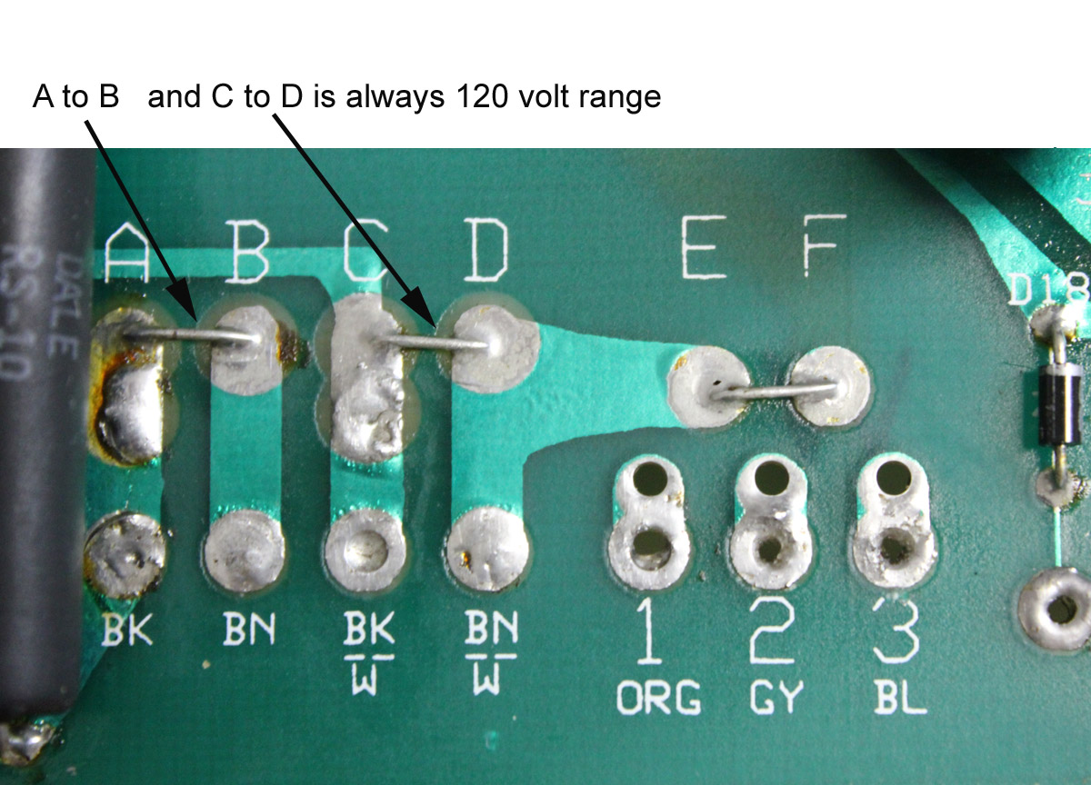
The
actual photograph below shows the buck boost not being used. This wiring setting
would be for a nominal 115/230 volts. These pictures
ONLY are for examples of jumper wire use. The board used for photo was not in an
amplifier. The board has no transformer wires
connected up from the bottom so the transformer pads are empty.
The following rules apply:
1.) NEVER SHORT 1, 2, or 3 TOGETHER.. Only
one number pad can connect to one letter pad.
2.) IT IS OK TO SHORT E to F, as long as a number pad is
not connected to E and F. This will give you 115/230.
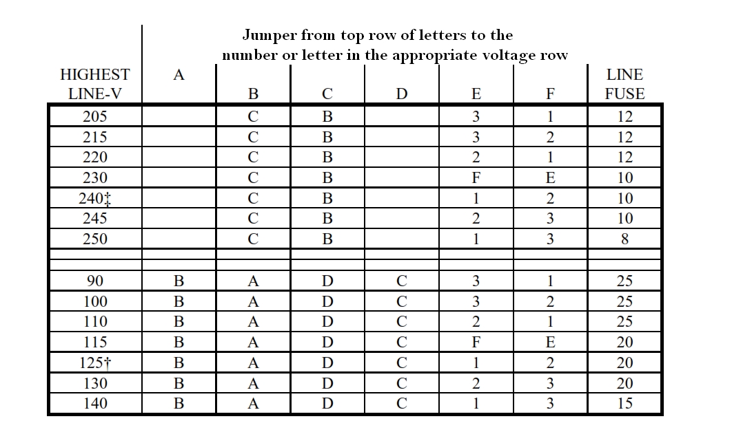
Note in the chart above how E and F will move between
either a short or to 1, 2 and 3!!
Trouble Locating Hints
10/05/2011
TROUBLE SHOOTING guide below
generally applies to many types of
amplifiers with suitable part number changes.
(In order of most
common occurrence)
Warning! Never test or operate a tube type amplifier
with the cover off and HV active! Always replace cover before powering up!
Virtually any issue can be located without activation of high voltage on an open
amplifier.
1.) Test on SSB using MOX or push-to-talk with no mic
gain. With no RF drive power, but the amplifier keyed, the
amplifiers grid current meter deflects about the same as the plate current
meter. This is a common problem
- D16 shorted (811),
D117 in AL80 series mainframe, including AL572. Negative rail meter
protection diode. This will also cause the plate and grid
current meter to track each other, and indicate false grid current- This problem is almost always from a defective tube or
tubes that have flashed over internally, generally from excessive
internal gas - This problem occurs after HV has
been shorted, arced, or
discharged to chassis - In older AL811H and AL572 amplifiers, grid
circuits using resistors should be
modified to current production
- This problem is almost always from a defective tube or
2.) Grid meter moves backward, and Ip meter reads
forward, with no drive and amplifier in standby
- Tube has a filament-grid short from shipping damage or
tube manufacturing defects- A shorted grid-filament shows as little or no RF
output power, and high transceiver SWR- Try removing all tubes, then insert tubes one in at a
time, to find bad tube
- Try removing all tubes, then insert tubes one in at a
- A shorted grid-filament shows as little or no RF
- Tube has or had an internal arc from gas or air
leakage- If a tube arced, a filament circuit component may
have shorted to the chassis. This could be a MOV on the filament winding
of the transformer, or a gas protection clamp tube under the sockets - A defective bypass capacitor may be shorting the filament or
the filament center tap line to ground
- If a tube arced, a filament circuit component may
- A backwards moving grid meter that never goes forward
is always an indication of a filament to ground shorts, either
inside or outside the tube
3.) Amplifier blows fuses when power switch is turned on
(always use proper 250V fast-blow fuses), blows step-start in other amplifiers
- Check for shorted tubes
- Remove the plug from outlet, remove the cover, and
remove the top white anode connectors from all tubes. Do not let the
white ceramic plate caps touch anything; lay them carefully on the tube
glass. Replace the fuses and cover, plug the amplifier in, and turn the
power on. If the amplifier powers up with tube plate caps disconnected,
a tube is shorted
- Remove the plug from outlet, remove the cover, and
- You can inspect the tubes for a silver area on the
plate (sign of overheating), or reconnect tubes one at a time until the
problem reoccurs to find the bad tube. Never connect the amplifier to
power lines with the cover removed - If fuse blowing continues, remove both transformer
HV secondary leads (normally red leads) going to the HV rectifiers
and/or center of filter caps (in voltage doubler) - If fuse blowing stops, reconnect one lead and
test. If fuse blows with just one HV lead connected, the transformer is
shorted - If fuse does not stop with both leads
disconnected, the amplifier may have a circuit problem *or* a bad
transformer. Can be either one - If fuse blowing stops with one HV lead connected,
the rectifiers might be bad, the filter caps shorted, or it might some
other HV circuit issue - If the problem is not resolved as above, defer service to
someone experienced with high voltage circuits
4.) HV/Plate Current meter reads flakey, tapping or
rocking switch while in Ip position makes meter jump around (AL811 series only)
- Dirty contact in rocker switch
- This is caused by switch manufacturer defects
- Flood switch with WD40 and rock switch several
times - If cleaning does not restore, replace switch
- Flood switch with WD40 and rock switch several
- This is caused by switch manufacturer defects
5.) Low Power Output
- This is normally weak tubes, ALC, or improper tuning
(see Tuning Supplement Sheet)- Normal RF power gain is about 12 times input
power. If drive power is 40 watts, the AL811H should produce 400-500 watts into the
antenna and 600-700 mA plate current - Weak tubes also often cause high input SWR on
all or most bands - Grid current should normally be 1/3 of plate
current when properly tuned near full output
- Normal RF power gain is about 12 times input
- Be sure your RF output meter is good (see Tuning
Supplement Sheet)- Check your radio power through meter with
amplifier off. Radio should be 100 watts using high power scale of meter
- Check your radio power through meter with
6.) Noise in receiver and/or erratic amplifier meter
readings on standby
- Bad tube or tubes
- Test as in step 2, problem similar to step 2
- Bad parasitic suppressor connection, resistor, or
inadequate parasitic suppressor inductance, this illuminates gas tubes on
filament transient suppressors- This problem only occurs on some bands, with some
PLATE control settings. It can be made to disappear by changing bands or
PLATE settings. - Squeeze suppressor inductors turns closer to
increase inductance - Ideal turns are now 6-7 turns for 811 tubes
- This problem only occurs on some bands, with some
- Alter biasing system. This is a new mod effective Mar
21, 2012 - Defective GDT (gas discharge tube) or defective MOV
7.) Audible popping noise and/or clicking noise
- Faint sharp ticking, might show in
receiver as noise- open RF safety choke on loading capacitor allowing
load cap to charge up and arc. Choke should be less than 40 ohms
- open RF safety choke on loading capacitor allowing
- Hollow louder muted click, might not
appear in receiver- Open bleeder/equalizer resistor across filter caps
- Bad filter capacitor
- Bad connection on filter cap area of power supply
- Open or poorly soldered plate choke winding connection
- Fan blade hitting something
- Speeds or slows with fan
8.) No receive or weak receive
- constant transmit light on amplifier
- Unplug relay line from amplifier
- If light goes out and receive restores, cable or radio connection
bad- If light remains on, problem inside amplifier
- bad connection in antenna system, tuner, or feed line
- try a different antenna system to see if it restores receive
- try moving cables or tuner switches to see if it restores receive
- no transmit light on amplifier
but still no or weak receive- Unplug relay line at amplifier
- if receives, problem in radio or relay cable
- Turn amplifier power switch off
- if receives, problem in amplifier
- Transmit through amplifier with amplifier power
or standby switch off- if SWR high, remove amplifier and substitute
double female barrel connector in place of amplifier. Make no other
changes- if SWR now low, problem inside amplifier
- if receive restored
- bad or dirty relay in amp
- bad or loose antenna system connection
- if SWR high, remove amplifier and substitute
- Unplug relay line at amplifier
9.) No or very little transmit power with amplifier on,
OK on bypass
- If amplifier transmit light does not light, short
relay line to ground- If transmit light works, problem in radio or
cable - If transmit light does not light, problem in
amplifier
- If transmit light works, problem in radio or
- If amplifier transmit light lights but no transmit
- High exciter SWR
- Output and input cables reversed
- Bad jumper cables
- Bad tubes, also see step 5
- ALC too high or bad tubes. Also see steps 2
or 5
- High exciter SWR
- If grid current is very high and there is no plate current
- No HV to tubes
- If HV is normal on HV meter, open plate choke or plate supply wire to
tubes
- If plate current is very high, grid current very low, tank circuit
problems - If plate current is very low, grid current very high, open blocking
capacitor, or tank circuit connection open
10.) VSWR goes intermittently high on the RF power output meter(s) when tuning
Plate or grid meters jump around with a steady carrier
while VSWR changes
- This is almost always some type of cable, antenna
tuner, or antenna system problem
o
Try tuning the amplifier into a dummy load with any antenna tuner
in bypass or direct
§
If the amplifier tunes up ok with the dummy load connected, you
have a tuner, feed line or antenna problem
o
Change tuner output to a dummy load, and tune into the dummy load
with amplifier in standby. Now try the amplifier
§
If the VSWR reads ok with the amplifier, you have an antenna
system problem
§
Wiggle cables behind amplifier to see if connector or cable loose
or bad
o
Check center pins of connectors to be sure poor soldering or bent
pins have not ruined connectors
§
Too much solder on male pin will ruin female connector
§
Unsoldered male or improperly assembled male will cause poor
connection
§
Some import cables and connectors are manufactured wrong size. Try
different cable for better fit
11.) Transmitter or transceiver SWR too high through amplifier, should be under
1.5:1
- Bypass SWR (amp on standby) also high, see step 9.
- Bypass SWR low, SWR only high when amplifier on operate
- Amplifier TUNE and LOAD improperly adjusted can slightly affect SWR
- Incorrect band selected
- Jumper cable between radio and amplifier defective
- Remove switches or devices between amplifier and exciter. Be sure nothing other than
a good coaxial cable is installed between amplifier and radio - Radio’s internal antenna tuner should be off
- Weak tubes cause a high input SWR on
all or most bands. see 1, 2, and 5 - Tuned input circuit problems
- Bias system problems (see 14)
12.) Grid meter pins with low drive power
- No plate current
- Open RF plate choke or no high voltage
- Low plate current that does not change with tuning
- Open tank circuit feed, open blocking capacitor
- Normal plate current and output, but grid meter pins hard
- Open grid shunt R8 1.5 ohm
- Can be caused by filament to grid/ground short or tube forced in
socket wrong
- Can be caused by filament to grid/ground short or tube forced in
- Open grid shunt R8 1.5 ohm
- Low RF power output
- Loading control too far meshed, load capacitor shorted, or antenna
system bad
- Loading control too far meshed, load capacitor shorted, or antenna
- Also see 1 and 2
13.) Amplifier does not appear to key, or does not release
- Disconnect from the radio. Ground the center pin of the relay line to
the amplifier.- If it works this way, you have a radio connection, radio
configuration, or radio component issue - If it doesn’t work this way, try a new relay line
- If the new relay line does not fix it, you probably have an
amplifier problem
- If it works this way, you have a radio connection, radio
14.) Bias system and meter problems
- Do shorted meter protect diode test
- activate amplifier in fixed bias amplifiers like AL1200 or AL811
series without drive power. Grid meter should not move, plate current
should move to normal quiescent current. - activate and apply a very small amount of drive (200 mW or less) in
auto bias amps. Grid meter should not move, plate current
should move to normal quiescent current. - If grid and plate meter move same amount the meter protect diode is
likely shorted - if plate current does not move to normal quiescent, it could be bad
tubes or a bias system issue
- activate amplifier in fixed bias amplifiers like AL1200 or AL811
AL811H TUNING SUPPLEMENT
2011 Oct 07