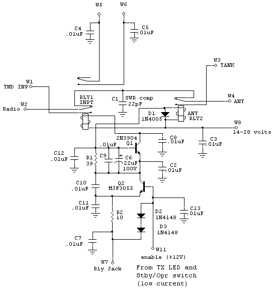
Ameritron TR T/R Relay Module
This is the Ameritron T-R relay module that replaces open frame relays in the
AL12 series of amplifiers. RLY1 is a DPDT 8 amp, and RLY2 is either a DPDT
8 amp with contacts in parallel, or a SPDT 16 ampere contact relay. This
circuit requires identical relay coil currents. Do not mismatch the relay coil
currents! Do not substitute other relays with verifying timing.
This circuit accelerates RLY2 closure. This will cause RL2 to be audibly
louder than normal upon closure, because RLY2 is accelerated. This does not
appear to have an observable effect on relay life.
Important Note:
W8 voltage and R1 resistance is determined by relay
characteristics. W8 voltage does not match the relay voltage! Sequencing
must be verified at the operating voltage, if any substitutions are made.
R2 determines relay coil hold voltages by setting relay hold current.

Q1 is a switch. Q1 holds the input relay off until C6 charges.
Q2 is a current limiter. Q2 holds maximum current to the total relay coil
current for both relays. This does things. It doubles the current
into RL2 when activating, because at that time RLY1 is held off, and it prevents
relay damage from excessive current. Q2, while only handling 70 mA at ~12 volts
maximum, is physically oversized, because it dissipates almost as much power
(0.84 watts) as the relay coils.
Operation:
The supply at W8 has to be much higher than relay coil voltage. W7 (relay
amplifier control jack connection) is limited
in open circuit and transient voltage to the voltage applied at W11. W11 should not be more than 12 volts
nominal.
In the off state, C6 is at zero volts. Q1 is held off. When the emitter of Q2
is grounded, the base is 1.4 volts above W7. Transistor Q2 becomes a constant
current source, approximately equal to .7/R2 = 70 mA
This allows 70 mA to flow through Q2. Since RLY2 has a high starting
impedance, and since RLY1 is held off by Q1, RLY2 sees almost full W8 voltage on
start. It also has the full 70 mA (double current) available. This closes RLY2 very fast.
As C6 charges, Q1 allows RLY1 to share current. RLY1 pulls in with a slight
delay. This delays the input and operating bias (W5 and W6) until after the
output has connected solidly to the load.
In the steady state, relay voltage drops to a safe holding voltage and
current.
Upon release of W7, RLY1 immediately drops. RLY2 is delayed by back EMF
current through D1.
It is advisable to never substitute relays, since this circuit is sensitive
to relay coil current and voltage.
Note:
These relays are 10-16 ampere rated hot-switching current
relays. They are some of the highest-rated current gold-flash contact relays with fast
response time available. The output relay has been tested to hold up to 14
amperes of RF current, in a steady state hold, at 30 MHz. This current is
actually higher than current of old open frame relays, which were limited by
flexible wire lead and contact spring carrier heating at 30 MHz. They are a vast
improvement in relay life and receive connection reliability. Like any
flash plated softer contact, they are easily damaged by hot switching. Be sure
the exciter does not transmit RF sooner than 3 mS after sending a relay closure
signal to the amplifier, or transmit RF more than 0 mS after signaling for an
open.