Battery Wiring
Safe Battery Installation Guidelines
Trunk Mounted Battery Installation
For the past 40 years, I have designed products that consume, produce, or
measure significant
current. These products are used on high voltage power mains and low voltage
systems. I also designed (and was responsible for production of) vehicle gauges
and test equipment, including instrumentation (meters) in products marketed by
national
suppliers. Our instrumentation customers included Snap On, Mac Tools, Sears, and others. You can skip all the technical stuff in the beginning, and just
move on to battery wiring
or to trunk mounted battery.
| The only connection to a battery post negative should be to another battery negative, the vehicle chassis, and/or the engine block. The battery negative If the negative power feed wire floats from all |
Battery Grounds, Accessory Grounds, and Equipment Grounds
The most misunderstood automotive wiring connections are connections to the battery
negative and ground loops. The
Negative Lead
page goes into details. Please read the
Negative Lead
page before connecting anything to a battery negative post or battery negative
terminal!
Directly from European wiring standards and regulations for vehicular
ancillary equipment:
4.6.4.
Negative Feed Connection
In the case of negative earth return
vehicles, the negative power line should not be fused.
It should be
connected to the vehicle body as close as practical to the point at
which the battery-to-body connection is made. Do not connect the
negative power line directly to the battery.
For heavy commercial vehicles (>7.5Tonne GVW) only, and those
vehicles with tilting cabs where the cab may be isolated from the
chassis by rubber mountings, a ground point is provided by the vehicle
manufacturer within the cab to provide battery to cab grounding.
Generally this is located within the main fuse box. It is recommended
that this point be used for installations in this instance.
With certain equipment it may be necessary to connect the negative
supply line to a local earth point.
In
this case an existing vehicle earth point must be used.
Technical Section Follows
| Conventional meters cannot be used to verify resistance of low resistance leads, especially starter or alternator leads
Occasionally,
|
Conductor Length, Conductor Gauge, and Resistance (background)
All conductors have resistance to electrical current flow.
Resistance
in conductors and connections is actually the ONLY thing that limits
current flow through wires. Conductor resistance causes voltage drop along the
wire’s length. Current through that resistance, and the resulting
voltage drop across that resistance, is actually what determines heating from
power loss. Resistance wastes power. Resistance, voltage drop,
heating, and current are all closely tied together with unbreakable electrical
rules. (There is something
else that limits current, reactance. Reactance is like resistance, but reactance
limits current without heating. Reactance only applies to rapidly changing
currents. Steady currents ware not affected by reactances.)
To keep things simple, let’s consider steady slowly-changing loads like
sensors, starters, lights, and other slowly-changing or steady dc loads. In the context of steady
or slowly-changing direct
current systems, we can ignore reactances. (We cannot always ignore reactances
when dealing with sharp pulses or rapidly changing voltages, such as pulsed fuel
injectors or ignition system pulses.)
This means in DC systems such as automotive wiring, or in normal home powerline frequency AC circuits, we have two things to worry about:
- Heat causing damage to a wire or things around the wire
- Voltage drop causing loss of available voltage to run things
DC resistance is directly proportional to conductor length for a given
conductor cross sectional area (conductor size)
and material, and inversely proportional to conductor cross sectional area for a
given length and material. A ten-foot long #14 gauge copper wire, with a certain
current, will drop ten times the voltage as an identical one-foot long wire.
This is why long wires sometimes have to be sized for voltage drop, and not
current rating.
Voltage drop along a conductor is
always current through the conductor times the conductor path resistance. A longer
path length through a conductor of a given size and
material, the more resistance and voltage loss that path will have. More current
flowing through a certain resistance produces more voltage drop and more heat. A smaller
cross section conductor creates more
resistance, and that results in more voltage drop and heat.
People like to tell us electricity is like water in a pipe, but that really
is not a good picture to have. Here is why…
People sometimes say wires are like pipes. This implies the inside dimension controls
the amount of current flow, just like water flow through a pipe. This just isn’t
true.
If we have a certain water pressure, a small “jet” or nozzle, or a small
section of pipe of almost any length, will
limit the maximum possible liquid volume that can flow. This is NOT
true with electricity! With electricity, any amount of current can flow through a
thin wire unless
the wire overheats, or the voltage drop becomes too much to run something
properly. Any size wire can handle any current, up to the point where the wire
overheats and melts, or the voltage drop does not allow the system to function.
Things limiting the amount of current
a given wire can carry are:
- Voltage drop from resistance along the wire
- This can result in low voltage at the far end, things might not run
properly if we are careless with resistance, conductor cross section, or
wire length
- This can result in low voltage at the far end, things might not run
- Damage from heat
- Heat is produced by current through the wire’s resistance, and how
quickly the conductor can get rid of heat
- Heat is produced by current through the wire’s resistance, and how
Current in a short length wire or conductor, if system voltage is high enough, is
limited by the safe wire temperature rise. A small size wire will not
restrict current flow, like a pipe does with water flow. Here is an example:
A number 10 AWG copper wire has about .001 ohms resistance per foot of length. If
we run 100 amperes through one foot of #10 AWG, voltage drop would be (100
amps*.001 ohms =) 0.1 volts. The heat, however, would be 0.1 volts times
100 amps, or 10 watts. This would make the 1 foot of wire pretty hot after a
short amount of time, even though voltage drop of 1/10th volt is barely noticeable.
This is actually how fuse links work. The short length of small gauge wire
reaches a fusing current, and the conductor melts.
Typical Fusing or melting currents of AWG copper wire, room temperature, no
forced airflow
| gauge | fusing current amperes | gauge | fusing current amperes | |
| 20 | 58.4 | 12 | 235 (typ alternator) |
|
| 18 | 82.9 (typ accessory feed) |
10 | 333 | |
| 16 | 117 | 8 | 472 (typ battery) |
|
| 14 | 166 | 6 | 668 |
The largest permissible
fuse, breaker, or fuse link allowed is determined by the wire size and
temperature rating…but we should never fuse at more than twice the highest
average or steady load
current.
Let’s say we are running a giant 12 volt 1200 watt spotlight. The spotlight
would have 12volts^2 / 1200watts = 0.12 ohms
resistance. With
12 volts at the light, the spotlight current would be 12/.12 = 100 amperes. Our #10 wire would add 0.001 ohms, reducing voltage by 0.1
volts. This would make load current 12/.1201 ohms = 99.17 amperes. Load voltage
would now be 11.9 volts. Load power
would be 11.9*99.17 = 1180 watts, instead of 1200 watts. This is hardly any change in the spotlight
performance, even though the spotlight current passes through a very small wire.
That certainly would not be true with water. If we passed water from a large hose
through a section of very tiny pipe, we would have almost no water flow at all!
We can see wire size does not limit current or power unless wire length
becomes so
long the wire’s resistance is a significant percentage of the load
resistance value, or the wire melts. A hose or pipe, on the other hand, limits
liquid flow based on size, shape, and pressure differential from inlet to outlet.
Shorter Wires are normally Heat Limited
This is because the total wire resistance and current determine voltage drop. Your house wiring, for example, is
normally sized by the heat that can be safely tolerated. Electricians and
building codes use a certain wire size for a certain current with little regard
to voltage drop. This is because they assume the wire is a reasonable length,
and the real worry becomes preventing house fires. At 240 volts, there
would be little worry about loss of five volts through a long wire’s resistance.
The length would spread heat around, and voltage drop is not a significant
percentage (about 2%) of total voltage for most household loads.
In some cases, especially where voltage is lower or wire length is longer,
voltage drop can be a significant problem. Vehicle
voltage, for example, is only 12.6 volts when running modest loads from a
fully charged lead-acid battery. While a
good alternator is charging, 12V
vehicle voltage can be slightly over 14 volts. If we allowed the same voltage drop as house wiring by setting wire size with
wire tables used for house wiring (by safe enclosed wall heat), we can easily
run into situations where voltage drop is excessive. If the resistance of a wire
or conductor dropped five volts in a 14-volt system (a 36% drop), the end result would
almost always be
devastating.
Because automotive voltage is low, we must pay attention to both heat and voltage drop
in high current wiring. We also should route wires for the shortest possible
length that looks good and is safe.
Some articles on Internet claim a vehicle ground should involve a large
copper buss connection, or the frame. While well-intentioned and laced with true statements,
the overall conclusion and some of the wisdom is not
true. The length of a ground stud or bolt is so short that resistance and
voltage drop does not matter very much. The biggest issue is having a good,
reliable, corrosion-free connection to the body shell and ground lug. If the
connection stud were three feet long, it would be another story. If you doubt
this, look at the bolt size in modern car batteries. Current comes out through a
fairly small terminal and bolt, neither of which is generally copper. As a
matter of fact, ALL of the connections in the battery are lead,
which is a terrible conductor! Why would any logical person go through the
bother of attaching a large surface area, short length, copper ground plate to
the body shell when the battery terminals and connections are lead?
It is easy to make insignificant things a worry, the old “making a
mountain from a mole hill” adage. Ground stud or ground conductor length is
usually so short and so wide or thick that the material resistance in the ground stud is one of the least
significant factors. Corrosion and clamping pressure is much more of a factor
than use of low resistance materials like copper. While copper terminals can be
good in some applications, like insulated power entrance bolts to very high current
devices like starting relays, starters, or alternators; copper studs or copper buss bars
are normally a very poor general application choice for body-to-lug or frame-to-lug
bolted connections.
- Body connections require high clamping force. Copper is generally too soft
for high tension, and
copper has
poor elasticity. - Copper also has corrosion issues. Copper readily forms an oxide that has very
high electrical resistance.
To avoid
galvanic corrosion,
we do not want two metals with significantly different electro-chemical rankings
in contact in the presence of salt and moisture. Materials choice varies with
the environment and application, and is far more than material resistivity
alone! Bare copper is generally a poor choice for a bolted ground connection
point in a car. Copper in direct pressure contact with steel will erode the
steel, and form insulating oxide layers. We are much better off using proper
stainless or galvanized fasteners, even though material resistivity is higher.
For a good ground connection, use a fastener that:
- resists corrosion or oxidation
- has adequate elasticity, or use a hard bolt and proper
tensioning
washer
Avoid soft fasteners, fasteners that corrode easily, or fasteners that cause
the vehicle metal to corrode. This rules out copper or aluminum in direct
contact with a steel or galvanized steel body.
Heat also causes resistance to increase, but this is normally a small or
insignificant change in proper sized and length wires. The change, near room
temperature, is about 1/2% per degree C. Hotter wires have higher resistance,
which is another reason to oversize long wires. Heat related changes are
negligible on short length wires, because they do not have that much resistance
to start with. Increasing almost nothing by a few percent is still nothing.
Longer Wires to Voltage Sensitive Devices are Normally Voltage Drop
Limited
Alternators and starters are usually the two things with the highest current.
An alternator might be required to output 100-150 amperes (which is always more than 2-3 horsepower load on the drive belt) and a starter might require as
much as 200-300 amperes. High current means we have to be very careful about
wire length and connection quality.
An operating vehicle normally gets 100% of its electrical energy from the alternator.
The battery primarily supplies cranking power, but also provides an increasing
share of electrical power as
alternator output falls below 13 volts or so. Excessive voltage drop in
alternator leads and connections, a slow spinning alternator, inadequately
sized, or defective alternators make vehicles battery dependent. At the same time excessive
alternator lead resistance makes the vehicle battery dependent, excessive
alternator lead resistance slows battery charging. The alternator should
turn at maximum permissible RPM at maximum engine RPM.
The alternator should feed the power distribution point of the
electrical system. This is why factory alternator leads almost always run
to the common point where electrical feeds branch, and NOT to the
battery post.
Long battery leads can cause slow cranking when hot. Long battery leads can
also ruin dynamic regulation of alternator voltage, and slow battery charging.
When battery leads are long, they should not be sized for current. Long leads
should be sized for voltage drop. Long battery leads almost always have to be
significantly oversized. Number 4 might be fine for a six-foot starter lead, but
it is almost always too small for a trunk mounted battery.
Running a ground lead from the engine back to a trunk mounted battery is a
common battery wiring mistakes. This adds unnecessary resistance. The same is
true for running the alternator output wire back to a trunk mounted battery.
Voltage drop for each 10 feet of wire (ONE direction) at normal starter
currents:
| Gauge | Resistance | Voltage drop @200 amps | Percentage loss (of 12.6V) | Percentage loss (of 10V) | Size recommended for distance** |
| 0 ga | .00099 ohm | 0.2 volts | 1.6% | 2% | 12ft |
| 1* | .00124 | 0.248 | 2% | 2.5% | 10ft |
| 2 | .00156 | 0.312 | 2.5% | 3.1% | 8.5ft |
| 4 | .00249 | 0.5 | 4% | 5% | 6 ft |
| 6 | .00395 | 0.79 | 6.25% | 8% | fuse link only |
*also typical maximum resistance from Ford Mustang trunk pan to inner
fender, with clean tightly bolted connections. Most of the chassis resistance
loss is in the sheet metal near the bolted connections, so front to back
connection distance makes only very small changes in resistance
** for negligible hot or extreme cold cranking
speed change with good battery and starter, assuming good connections and ground
return
Connection and ground return resistances add to this. If you have #2 fifteen
feet long, the wire loss would typically be about 5%. The return loss would be
about 2%. You would lose about 7-8% total of battery voltage, plus connection
losses. This will noticeably slow a hot starter, but should not cause start
problems with a good battery and starter.
Frame or Body Connection?
In a vehicle, the steel shell is almost always better than a sub-frame or
frame connection point. A typical body shell has large stamped areas. These
areas are normally welded at
multiple points to surrounding panels. Body panels and the body shell have a very large surface area. The
large surface area provides
solid electrical connections. Because area is so wide, even a thin panel has a
very large cross-sectional area.
Sometimes frames are
isolated from the body by rubber mounts. My F-250 truck has virtually no
cab-to-frame or fender-to-frame electrical bonding, so the wide body shell does
not contribute to electrical ground conduction cross section.
In the case of a unibody, the frame is an
isolated stamped structure. It is spot welded to the body shell at a few dozen points.
The (sub)frame is probably OK, but it is certainly no better than any other
panel. There is no reason to use the (sub)frame on a unibody.
If the body shell is a non-conductive material like plastic, carbon fiber, or
fiberglass, use the metal frame or a very large auxiliary ground buss conductor.
Avoid ground connections through bolt-on or hinged sheet metal, such as
fenders, hoods, trunks, and doors.
Unless you have a fiberglass or non-conductive body shell, or have something
isolated on rubber mounts like a truck, don’t waste time and material running extra
ground lead length to a frame or cage. Such connections, because of the extra
path length, usually have more resistance than short direct connections to the
shell. Try to use radiator supports, inner fenders, firewalls, floors, and
other large permanently integrated parts of the vehicle that are close
to the thing you want to ground.
| Example of ground path resistance: Resistance of any uniform conductor is A number 1 AWG copper wire has an effective diameter of about 0.3 Let’s assume a steel body shell is about 16 gauge, or about .06 The resistivity of steel is about 15 ohms per 10-6 cm. The This means a one foot wide length of steel body shell, if that shell A four foot wide area of floor pan, just .06 inches in thickness,
|
Battery Wiring and
Connections
Car manufacturers are careful with wiring and parts. Manufacturers almost
always choose parts and wiring for very good reasons:
1.) Safety. It is expensive to damage cars or people
2.) Reliability. It is expensive to warranty many thousands or millions of
unreliable products
3.) Cost. They have to meet 1 and 2 and not waste money. They are in
business, not in a hobby
Things to Avoid
Alternators have a voltage regulator, either internal or external. The
regulator system adjusts alternator voltage by changing the magnetic field level
in the alternator. The regulator always tries to maintain a certain voltage, but
the voltage for a given field magnetism is entirely dependent on rotor
(armature) speed and magnetic field level. No matter what alternator we use, the
internal field cannot change instantly. It takes time for the iron inside the
alternator to respond to changes in applied current from the regulator, and for
the magnetic flux levels to change. This creates a response lag as the
alternator readjusts to load and input shaft speed changes.
Because of this unavoidable response lag, the system depends on a large
storage capacity battery to act like a damper or electrical flywheel. The
battery absorbs voltage surges until the alternator catches up with the
regulator, if the load is abruptly decreased, and the alternator has a power
surplus. The battery supplies voltage, if the load suddenly increases, until the
alternator catches up with the regulators call for more power. The battery
stabilizes the electrical system and prevents spikes and dips.
Without a battery, an alternator’s voltage can surge over 100 volts with an
abrupt load change. As a matter of fact, removing the battery in a system with a
steady electrical load and charging battery can cause a very large voltage
surge, because the battery’s charging current is removed along with the
battery’s ability to dampen any voltage surge! I’ve actually seen headlights
burned out from a bad battery connection, let alone more sensitive computers and
ignition systems.
Because of this response lag and danger of surges, the battery must
never be removed from a running system. The battery must always have a
reliable solid connection.
This is the very reason alternators wire directly to bolted battery
connections with fuse links, and manufacturers do not use conventional fuses,
circuit breakers, relays, or switches between the battery and the electrical
system. This is why the normal wire routing is alternator output to battery
positive common point, and fuse links are used instead of fuses or breakers.
This is why there is never a switch or relay between alternator output and the
battery positive common point.
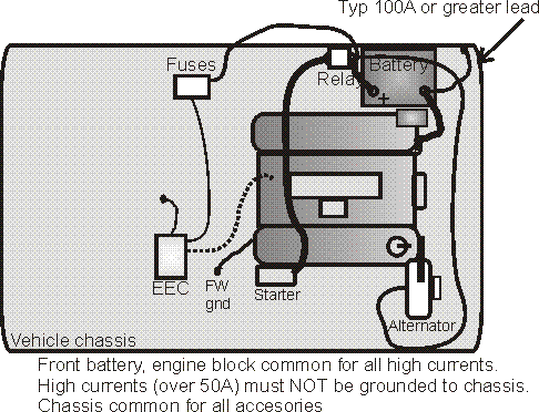
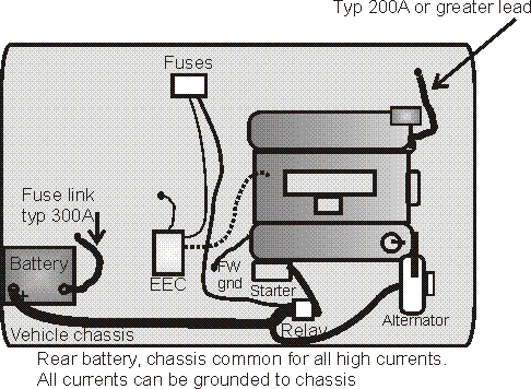
A properly designed OEM basic circuit layout looks like this:
The common connection point is where alternator, battery, and loads all join.
Notice if any fuse or fuse link opens, the battery remains connected to the load
or the alternator. It is impossible for the battery to be accidentally removed
with the alternator connected, other than a battery terminal or battery failure.
With almost any automotive electrical system, a very good, reliable, battery
to alternator and starter ground connection is critical. Automotive manufacturers almost always have the
very heavy battery negative lead directly to the engine block or some very
solidly attached major component. This is because alternator charging currents
and starter currents, the two most significant current paths, must be kept out
of small wiring. High currents must not depend on or pass through unreliable connections.
Unreliable connections not only include physical connections we visually recognize as
“terrible connections”, but also include engine components
that are not securely and solidly grounded to the engine block. One example of a
poorly grounded part might be a manifold, which floats from the heads and block
by gaskets. The only ground path to the block is through the manifold bolts,
which can become corroded or insulated with thread sealers.
Loctite and other thread locking compounds make
pretty good insulators. I’ve seen thread locker compound completely isolate bolts
or screws from
the components they thread into. Even when physically tight, most thread locking
and some thread sealing compounds can electrically insulate bolts and screws.
The general rule is if a compound penetrates and hardens, it can electrically
insulate an otherwise tight connection. Do not rely on connections or rely on
ground current paths that might run through penetrating thread locking
compounds, like Loctite.
On the other hand, silicone grease and anti-seize compounds will actually
preserve electrical connections. They keep air and moisture away from the bare
metal areas that physically touch.
Abnormally
heavy loads, such as heavy-duty cooling fans, exceptionally large audio amplifiers, or two-way radio
systems, must also have reliable ground paths to or from the battery negative. Unless
a heavy external load is ground isolated, the external device should not attach
directly to the
battery heavy cable. The battery should be grounded to the vehicle chassis, and
external devices with negative leads connected to chassis paths should have
negative grounds connected solidly to the vehicle chassis.
| With distances more than a few feet, the chassis path through any steel unibody vehicle is far less resistance than any practical size of copper cable, and any common frame. Use the chassis for long grounds, such as from a rear mounted battery to the front. The only requirement is a good connection to the unified sheet metal. Be |
Battery currents and
other high currents to alternators or high current loads (like starters or
cooling fans) must never be allowed to flow across high resistance ground paths.
Allowing high currents to flow across poor connections causes
service related issues, like slow engine cranking and unreliable accessory
operation. Poor ground connections can permanently damage expensive parts, such
as wiring harnesses
and electronic
engine control systems.
Front Battery System
Battery negative grounded to vehicle chassis through smaller, but
secure, secondary lead for accessory and light currents. Never omit this
battery-to-chassis wire!
Battery cable negative heavy lead runs directly to block or to
a large metal-to-metal contact major engine component (not insulated by
gaskets). Never ground the very heavy high-current lead to vehicle chassis with front mount batteries.
Always ground the heavy lead to the block, bell housing bolt, or some other
solidly-connected (no insulating gaskets) engine component.
The rear-of-engine to firewall ground braid, like the hood
ground people often remove, is primarily for electrical noise reduction.
This ground lead can be a smaller braid to an unused head accessory mounting hole, or to a
bell housing bolt. Never put ground lugs under a tension-critical bolt, like a
head bolt. Lugs are too soft and will yield, causing unreliable bolt torque.
The alternator grounds to the block or head through alternator
brackets. The alternator is somewhat less critical than the starter current
grounding point, because peak alternator current is less than peak battery
current.
Always remember, battery currents can be as large as several hundred amperes.
We do not want even a fraction of that getting into bearings or into electronic
engine controls. Front-mount batteries should always use a very heavy negative cable to the engine block, or
to some other engine part like a bell housing that is reliably and securely
bolted to
the block. The large negative cable is the primary path for starter currents and alternator
battery-charging currents. While generally not the first choice, unused head holes are usually
OK for these connections.
A critical path that is often ignored, or accidentally removed, is
from the battery negative or engine block to the vehicle chassis. There
must be a reliable battery negative-post to chassis connection. Without a
reliable connection, the vehicle chassis can electrically connect to the
block through engine and
transmission
bearings. This can not only damage bearings through arc pitting of bearing
surfaces, it can also cause intermittent or fluctuating voltages to appear in
critical or sensitive vehicle electronic systems.
Electrical potential difference between the block
and vehicle chassis will often show as voltage impressed upon ground leads of
electronic controls and sensors. Even a small voltage difference between the engine block
and vehicle chassis can change sensor readings at the EEC.
The battery-negative to chassis connection for a front mounted battery only needs to be 50-100 ampere size.
This is because, with a heavy battery ground cable to the block, starter current
and charging current does not pass through the vehicle chassis. The small
battery-to-ground connection runs accessories that return through the body shell
to the battery and alternator. These accessories include lights, electric
motors, audio equipment, gauges, and electric pumps. These shell currents
normally amount to less than 40 amperes.
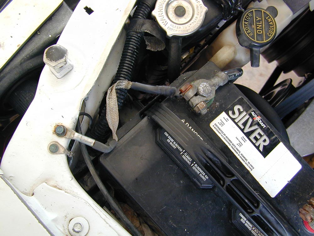
Some time before
I purchased my used 1989 Mustang, someone replaced the battery cables. They
neglected to use a two-wire negative cable terminal with the smaller chassis ground wire.
To repair the missing ground in the front mounted
battery situation, I soldered
flexible braid to deep lugs (McMaster-Carr is a good source).
Heatshrink sleeves reduce flexing at the connection points, preventing
fatigue failures. The connections are cleaned, and then coated with pure clear
silicon grease (tune up grease or dielectric compound) in contact areas. The
grease keeps water and air away from pressure connections, keeping them clean.
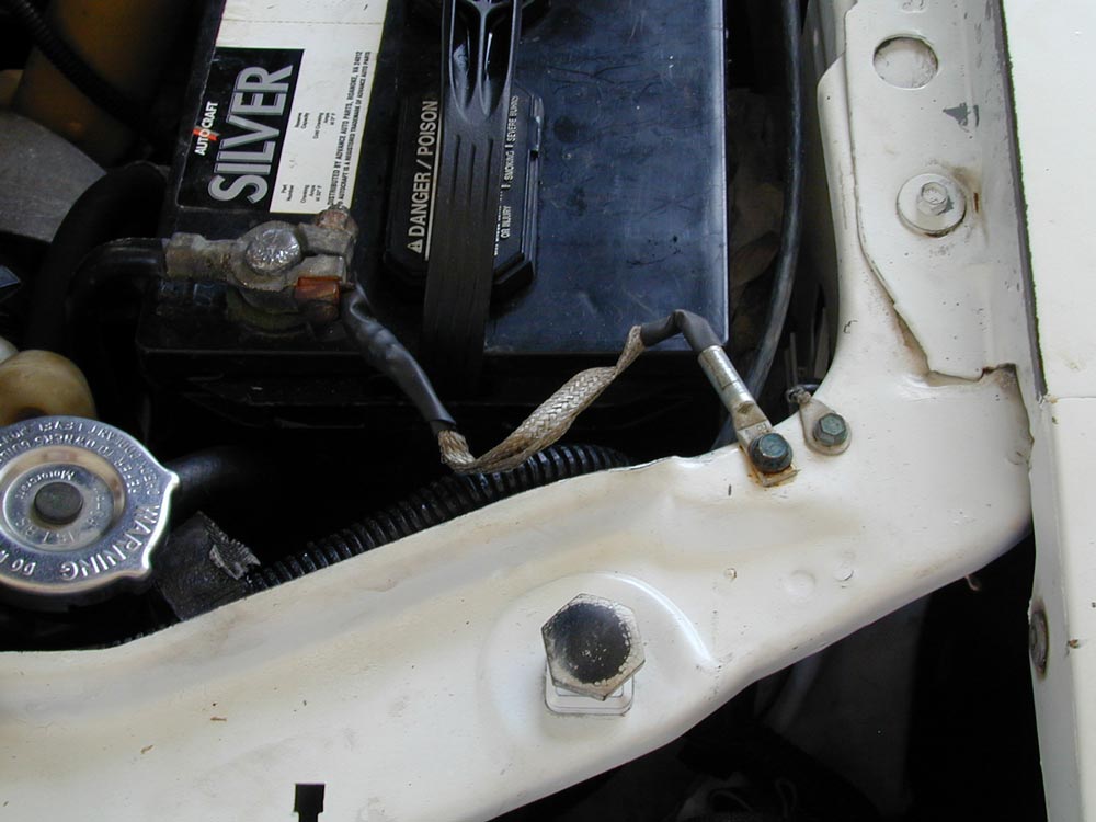
The very thick, black, negative battery post lead goes directly to the engine
block. This is the lead that carries alternator and starter currents. These
currents can be in the hundreds of amperes.
All vehicle accessory power, including lights, radio, ignition, fan motors,
wipers, and computer typically run negative from the vehicle chassis. The
negative battery post small lead should be securely grounded to a solid piece of sheet metal that is
welded to the main vehicle chassis structure. In this example the radiator
support works. Whoever replaced battery cables in my 1989 Mustang never grounded
the battery negative to the chassis. Don’t make that mistake! Working does
not mean it is right!
Without this critical ground from the battery to the chassis, voltages to
the computer and other important electrical devices become unreliable. To be sure the engine block
stays at chassis, I also have a wide ground braid on the rear of the head to the
firewall. This makes sure engine sensors are at the same ground potential as the
computer chassis grounds.
Welded large panels anywhere in the chassis of a unibody vehicle have very
low resistance. Despite what some people might claim, the unibody chassis makes a great low resistance ground path all through
the vehicle. You will probably never do better than the body shell for connection path resistance.
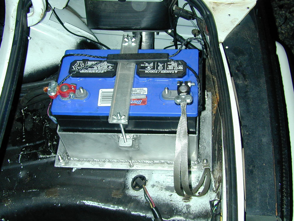
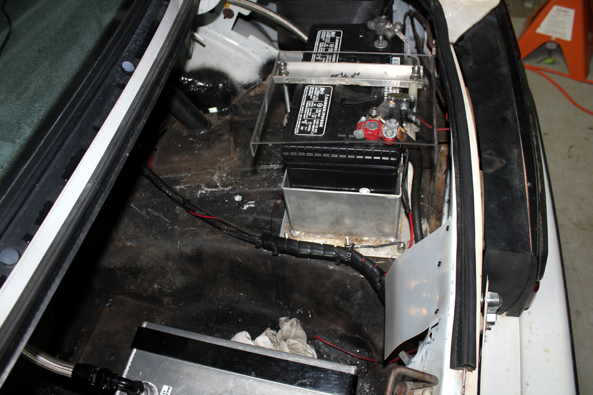
My trunk mounted
battery:
Trunk mounted batteries in metal chassis vehicles are a very special wiring
situation. With a rear-mounted battery, we have to get the high starting and
charging currents to the engine block with minimum resistance and high current
capacity. Do not run a ground wire to the battery unless the
vehicle chassis is an insulating material, like fiberglass. The vehicle chassis
should be the ground lead. The battery should be high-current grounded to the vehicle chassis with short direct
leads. The engine block should be high-current grounded to the vehicle chassis.
This is how I handled my car, and it starts in any weather at any temperature
just as a front battery would.
The engine block is grounded to the chassis through a heavy “starter size”
cable.
The battery should be grounded through a fuse link or fusible braid that
fails at less current than the main battery feed cable. This way, if the
positive cable shorts to the chassis, the negative lead disconnects the battery.
Nothing else connects to the negative post.
Alternator output, 12V fuse block feed, and battery share a secure common
connection point.
To increase traction, and to have more room and less weight in the front, my battery
was relocated to the trunk. I mounted the battery as far back to the right rear
as possible, because that tire “lifts” from drive shaft torque and has the least
launch weight. The further back and higher the battery, the more weight
transfers. The extra mounting space allowed use of a large, deep-cycle, marine battery.
I selected a deep-cycle battery because normal sealed lead-acid batteries permanently lose charge capacity with any excessive
discharge. A single deep discharge can ruin a sealed lead-acid battery’s
ability to store charge. Deep cycle or deep discharge batteries are much more
immune to accidental or intentional deep discharge cycles.
Prior
to clamping ALL
bolted or clamped
connections (except
solder points) are
cleaned and given a
light coating of
clear silicon
dielectric grease. This grease is also called “electrical tune-up grease”.
Anti-seize compounds or Noalox also work to prevent corrosion, and preserve
electrical connections. Be sure the grease you use is compatible with the
metals.
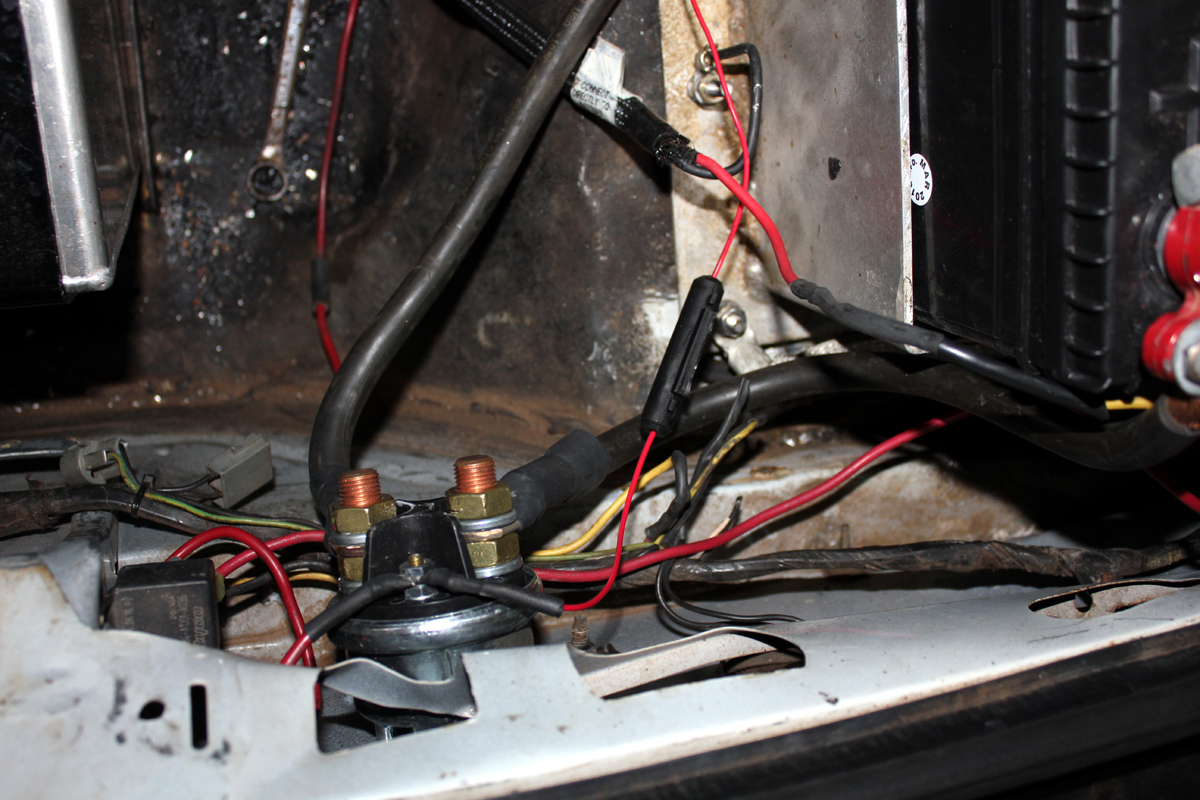
Battery hot wire
is 2/0 (“two-ought”) welding
cable, about 15-feet long. Welding cable has a tough heat-resistant jacket, and
is extremely flexible for its size. This cable runs directly to
the starter relay
battery post on the
starter. The lug at
the starter, since
it is exposed to water and dirt, is
soldered on. The lug is close fitted to the welding cable. I heat the lug with a
butane torch, and flow rosin core solder into the lug, totally flooding the connection with
solder. To
keep the cable’s insulation from melting during soldering, I wrap the cable insulation with a wet rag.
Wiring up front can be a little tricky. My Mustang wires the car like this:
Starter connections
There are two basic types of starters:
|
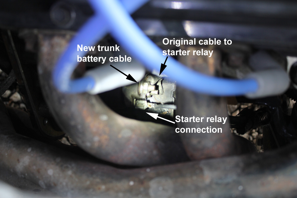
The 89 LX uses a starter with an external solenoid system, and a start relay.
This system requires two wires to the starter. One wire is a very large high
current wire to run the starter motor, perhaps around AWG 2 size. This wire
bolts to a high current stud on the starter.
The other starter wire is much smaller (it has a push on spade lug), since
this wire only has to run the solenoid winding. This wire is probably around AWG
10 size.
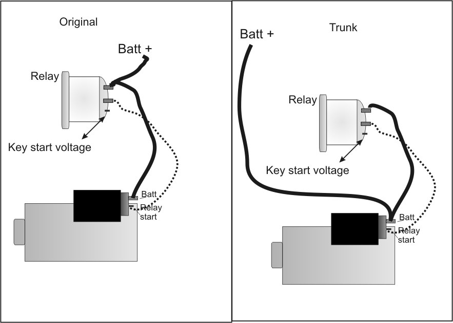
My Mustang’s factory circuit looked like this:
Since the starter had a large gauge feed from the battery common point to the
starter, and since my battery is on the PS rear, I simply back fed the battery
from the starter solenoid. This makes the feed wire from the rear to the starter
high current post very short, ensuring maximum voltage to the starter. If
it did not have this starter type, I would have had to run the rear battery wire
directly to the start relay post.
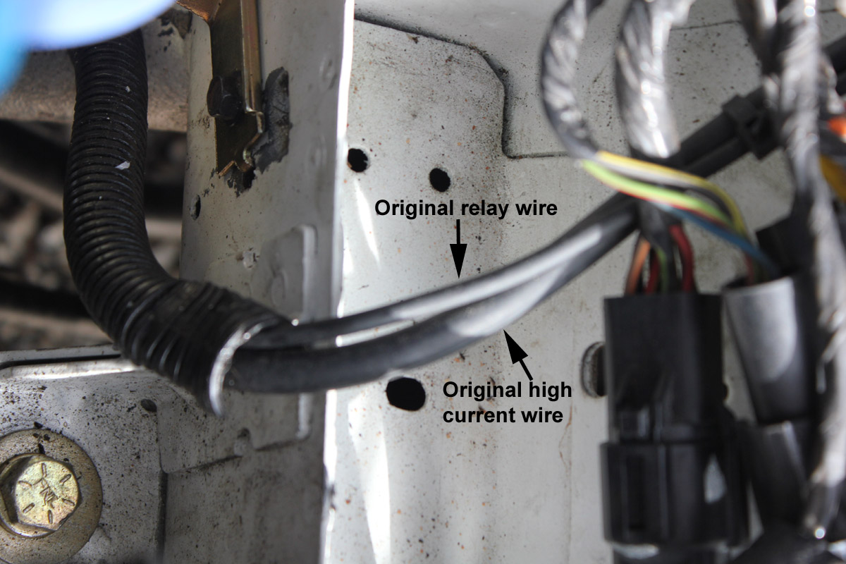
The old,
heavy, starter feed
wire from the battery side of the start
relay is now shared with the large lead from the rear battery at the starter
solenoid post, and the original
starter feed wire now back-feeds
the electrical system. The smaller wire with push on lug, as was used originally, runs the starter solenoid coil.
It is switched 12 volts from the start relay.
Picture Below:
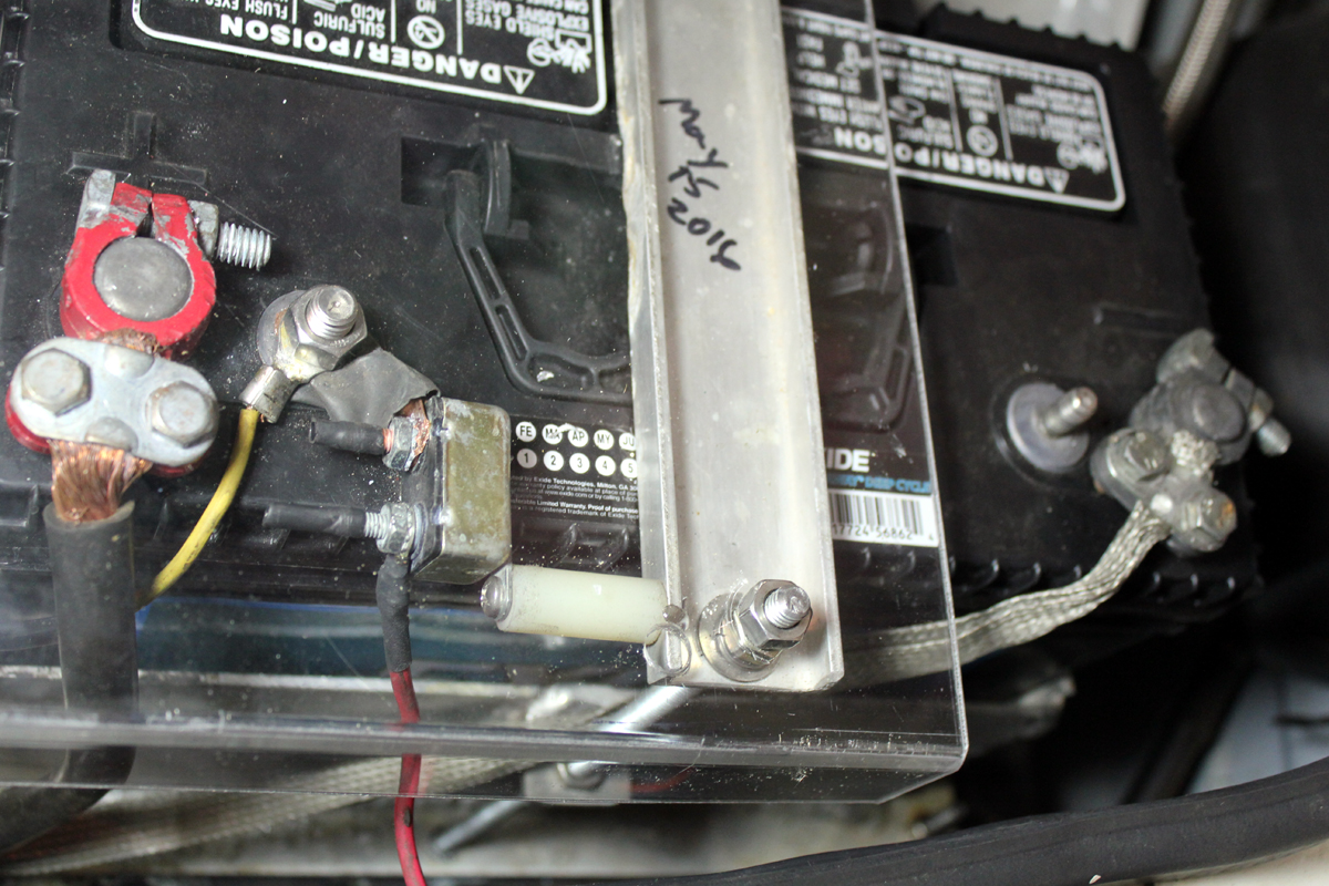
Battery ground
straps are 3/4 wide
by 1/16th inch thick
tinned strap with
carry current rating
of 150 amperes. Two
equal lengths are run in
parallel. These
straps have low enough resistance to not drop excessive battery voltage. They do
not heat
under normal conditions, but will act as a
fuse if the welding
cable should ever
short to the
vehicle chassis (such as in an accident). The bottom
lug is crimped and
soldered. The
battery post
connection only
crushed by the battery terminal cable clamp.
Some
sort of reliable
fusing is mandatory
for fire protection.
The fuse links must
melt before the 2/0
welding cable melts, and must melt before the
battery
significantly heats
or melts.
The battery box is homemade. I cut, bent,
and welded it here after an
unsuccessful job (it leaked) done by
a local welder. This
box is water tight
aluminum, and it is held down
by six 1/4-20
stainless screws.
Stainless screws
with stainless star washers (to bite into the metal) sandwich the
vehicle chassis. They are nutted to the trunk floor metal, so they act as studs.
They are also coated with silicon grease. These “studs” hold the
box and also
provide the ground connection.
This creates six parallel ground connections to the vehicle chassis. A sealed plastic box
fits over the
battery and vents
outside the car to a
low-pressure area, preventing hydrogen gas
accumulation in the
trunk.
The battery is a
large heavy Marine
deep-cycle battery.
The battery is mounted on the
right tire side, mounted as
high as possible,
and positioned back as far as
possible to place
maximum weight on
the right rear tire.
This caused a
significant increase
in traction with the
street radial tires.
This lead-acid deep
cycle battery was
selected because it
has a very low
internal resistance. Standard batteries lose ability to store charge if allowed
to discharge below 12.6 volts. One deep discharge cycle can ruin some regular
batteries. A deep cycle will not lose charge storage capacity when
allowed to drop
below 12.6 volts.
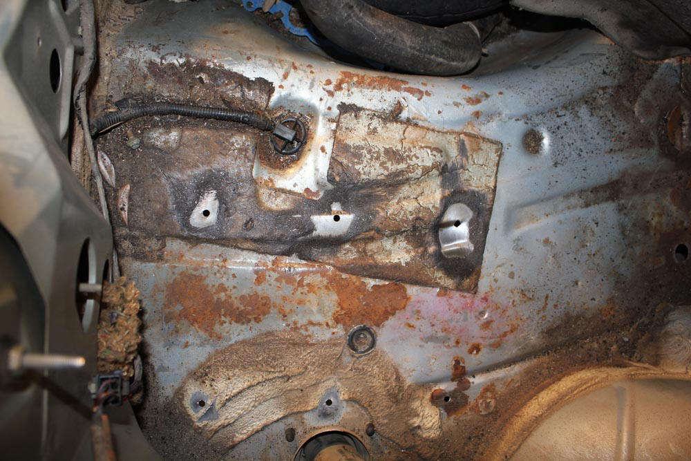
This is how I just did a 1994 Mustang the same way as my 1989. This is the
trunk floor hole pattern. Notice we wire brushed the area around the holes until
the galvanizing shows.
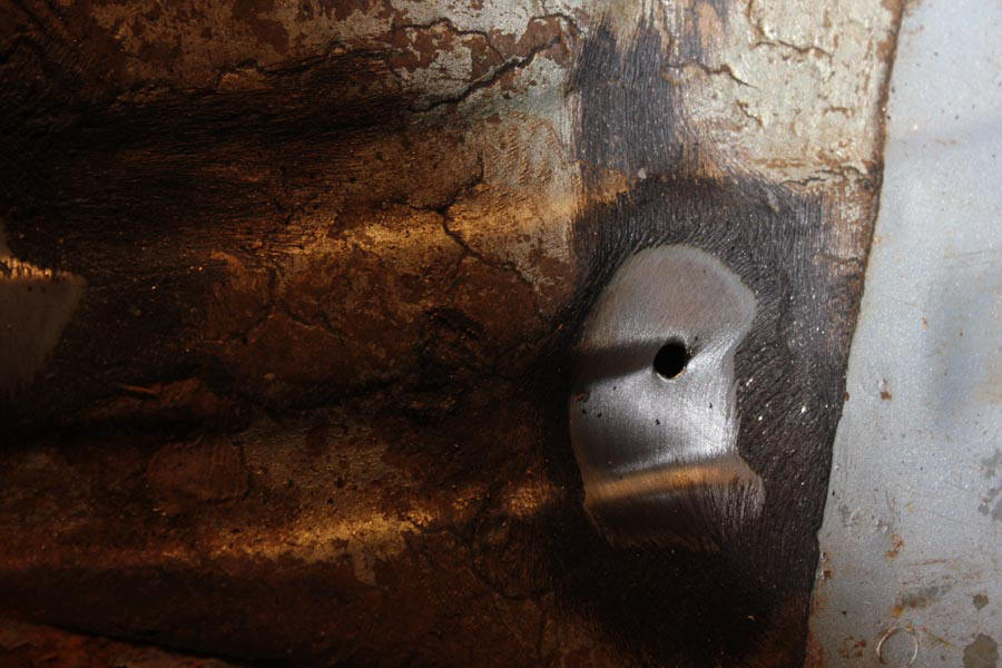
Close up of a hole in the 1994:
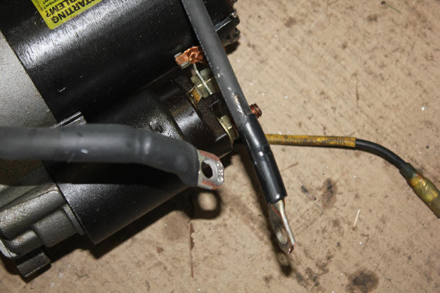
The starter and power wires prepared with protective sleeving and lugs for
the 1994 ready to fit the starter terminal. I soldered the lugs on:
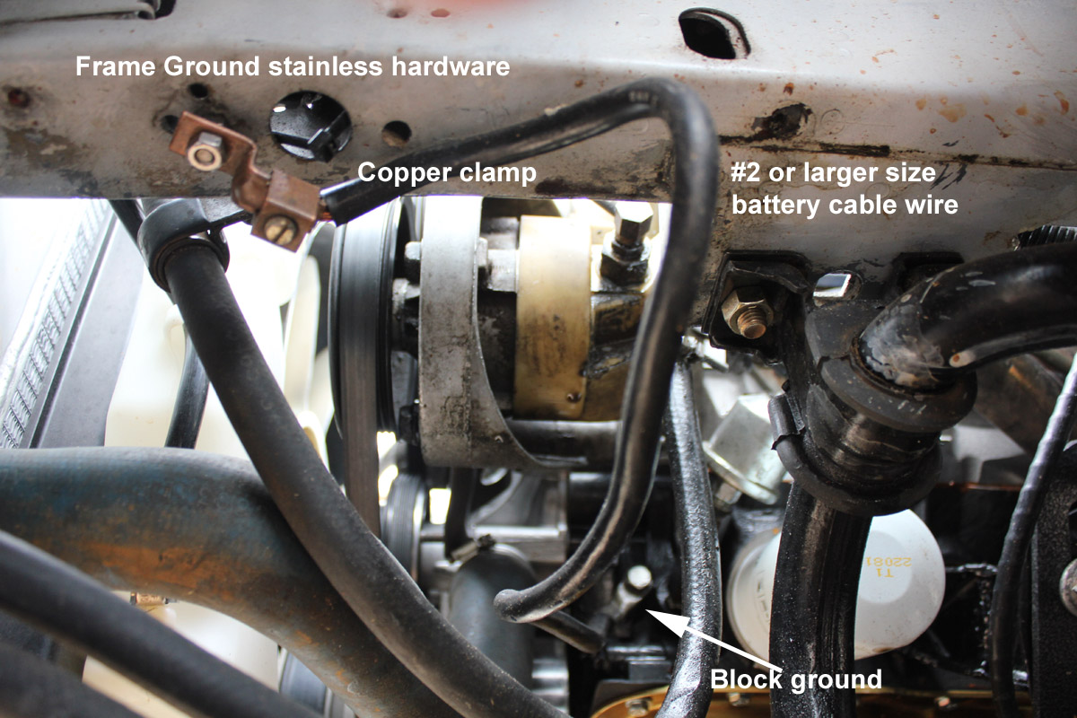
I cut the old
battery negative
lead and added a
good high-current
wire terminal clamp for the high current ground
connection. I used a handy copper compression lug for metal compatibility from
the copper battery lead to the lug, although a soldered lug like on the starter
would have probably been better. I coated all connection points with silicon
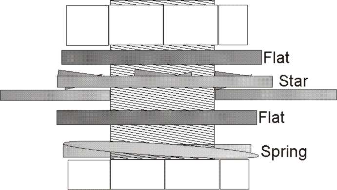
dielectric grease. The
actual body
connection is
through a 5/16
stainless bolt with
a stainless steel tooth star
washer directly against the sheet metal on the dry side, a stainless spring
washer on the bolt
head, all buffered by stainless flat washers. There is grease between all layers
to seal out moisture.
This stack forms a tightly-connected stud for connections to sheet metal. A
second nut with
spring or split-ring
tensioning lock washer and
stainless flat
washers holds and
buffers the copper
clamp or lug, preventing
direct contact between copper and
the galvanized steel car body.
This area was
also cleaned and
coated with
dielectric grease
before bolting. This is the proper way to do a ground stud on sheet metal.
Use dielectric grease on all electrical joints, and between sheet metal and
any washers.
Dielectric grease will keep moisture out and preserve
the connections.
As a personal opinion, I think the NHRA and racers need to work more on
electrical, nitrous, and fuel safety. There have been several incidents within
the last year of preventable deaths or severe injuries. Cars today have become
unbelievably fast. My street 1989 Mustang LX, even with the small turbo engine
and mufflers, goes well over 100 MPH in the 1/8th mile. With that speed comes increased
danger.
My personal rules are:
1.) everything has to be properly fused at the voltage source end of any
wires
2.) no fuel or nitrous inside the passenger area
3.) no high current wiring in the passenger area
4.) firewalls between fuel and passenger compartment and between
engine and passenger compartment
5.) automatic fuel shutoff in a collision
6.) ignition key kills all switched power
7.) I always wear a fire suit
One of NHRA and IHRA rules deals with a rear battery cutoff switch.
While generally poorly written and conceived, it is still a rule. This how I
meet what seems to be that rule’s intent. Many of the things I do are not
required by rules, although I think they should be.
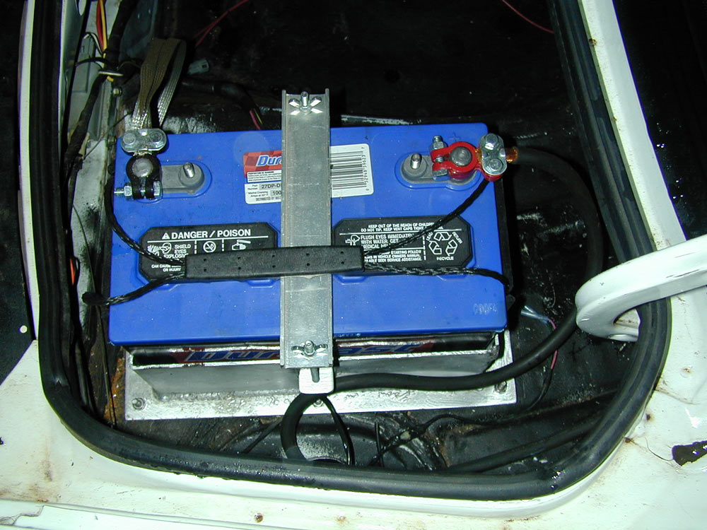
For performance reasons, my installation places the battery as far back as
possible. This is a heavy deep cycle Exide battery. Note the battery length is
parallel to the rear. This puts the cell plates at right angles to normal G
forces. This will slightly reduce long term flexing and stress on battery plates
plus, in a wreck, the load force would be distributed over the largest battery
surface.
The highlights of my system are:
1.) Battery and switch positives are covered to reduce chances of accidental shorts to
ground
2.) Battery tie down is through the floor to a plate
3.) Battery is positioned sideways to normal G-forces, and as far to the rear
as possible for traction
4.) Battery is retained in a water tight aluminum box to catch acid leaks
5.) The battery box is internally padded with rubber
6.) The battery box has multiple ground bolts that also hold the box in
place. These bolts and the box form a low resistance distributed ground
7.) The battery is catastrophic fused by the negative strapping. Fusing
current is approximately 350 amperes
8.) Leads are protective sleeved and secured from vibration
9.) Low current “keep alive” leads are fused with low amperage fuses
10.) A main pole kills the high current feed, while the fuel pump and
alternator field run through a second pole. This kills the engine, alternator,
and all electrical except low current fused keep alive memory
11.) The fuel pump feed is fused with a 50-ampere auto reset breaker
I write the battery install date on the hold down.
In addition I have a rollover fuel valve and a fuel pump power impact sensor.
In the event of an impact, fuel pump power is cut. No fuel or high current lines
exist inside the passenger compartment.
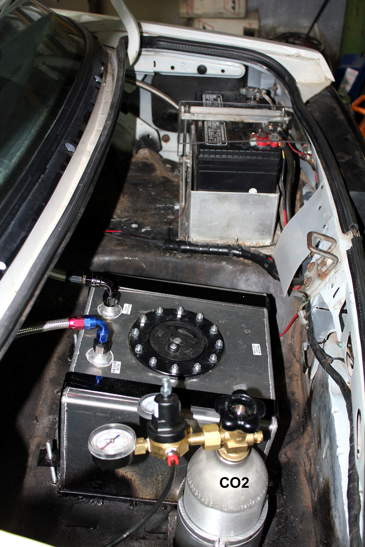
Uncovered view before wire lacing: