Audio, Power, and
Control Lines
RF Feedback, Hum, and Distortion
Improperly connected
or configured audio
and power supply
lines can cause hum
or distortion in
audio systems. This
includes
microphones,
headsets, computer
sound cards, and
nearly any other low
level audio system
or device.
RF feedback is characterized by anything from a little distortion causing a
slightly rough sound on transmitted audio, to highly-distorted, unintelligible,
raspy bursts of audio. The gateway for RF feedback is always an equipment design
limitation.
RF feedback, and even hum and noise ingress, requires a few things. First, the
equipment must have some sort of
shielding or wiring error, inside or outside the equipment. The wiring error
or imperfect shielding allows RF feedback, but does not actually
cause RF feedback. Less-than-perfect shielding and wiring technique problems are
called to our attention by excessive common mode RF currents, or
by exceptionally strong direct fields from nearby transmitting antennas. The
problems are not actually created by the excessive current or
field levels, but by a mix of design problems. Since problems are level
sensitive, anything that increases electric or magnetic field levels, voltage,
current, or power can highlight wiring and equipment shortfalls or problems. The
true cause is less-than-perfect shielding and/or wiring in the presence of a
problematic field level, current, or voltage. An ideal design has a reasonable
compromise between equipment design time and cost, and allowable common-mode RF
current levels and/or local field intensity levels.
Audio systems and RF systems behave the same in many ways, and behave quite
differently in other ways. For example, at audio frequencies shield dc
resistance is critical. At very high radio frequencies, gaps in braid and the
angle of braid weave, control leakage. At very low frequencies shield resistance
and material can be critical, while small gaps or weave angle might be
meaningless. At radio frequencies, aluminum works as well as (and often much
better than) steel for shielding magnetic fields. At audio frequencies, steel
might be required to stop magnetic flux leakage.
At radio frequencies, even a very thin foil can be many skin depths thick. This
is because the shield is not thick compared to
skin depth at low frequencies.
Nothing passes through the shield, neither magnetic nor electric fields. This is
true even if the shield is thin aluminum foil, and braid thickness or shield
thickness is nearly meaningless.
To be most reliable with reasonable equipment cost and wiring complexity,
designers must understand balanced systems, unbalanced systems, shields, audio,
and RF system behavior.
SSB transmitters draw a very large portion of dc power supply current in direct
proportion to audio input levels. The dc power supply negative ground lead can
modulate a low-level audio line with the rough “brah
waah braah” sound of
SSB without a
carrier. Many
“RF-sounding”
problems are
actually caused by
low frequency ac or
dc ground loops from
power supply
negative leads,
acting in concert with other grounding, wiring,
or shielding shortfalls.
Treating Audio Lines
Correctly
In the early 1970’s through 80’s, I worked at various broadcast stations. Much
of the work was wiring studios and switching racks, which employed hundreds of
line-level audio feeds.
One very basic rule
was followed by better, more-experienced audio and
broadcast engineers. Never ground a shield at both ends of
signal paths between different pieces of equipment. An audio
shield, or any
ground return lead
with low-level
audio, should only be grounded at the audio
device’s input port, or at one end of a path.
This prevents inducting noise and hum from ground loops between
device cabinets, which are almost always at slightly different AC potential.
This rule is often ignored by
amateur radio
operators and amateur radio equipment manufacturers.
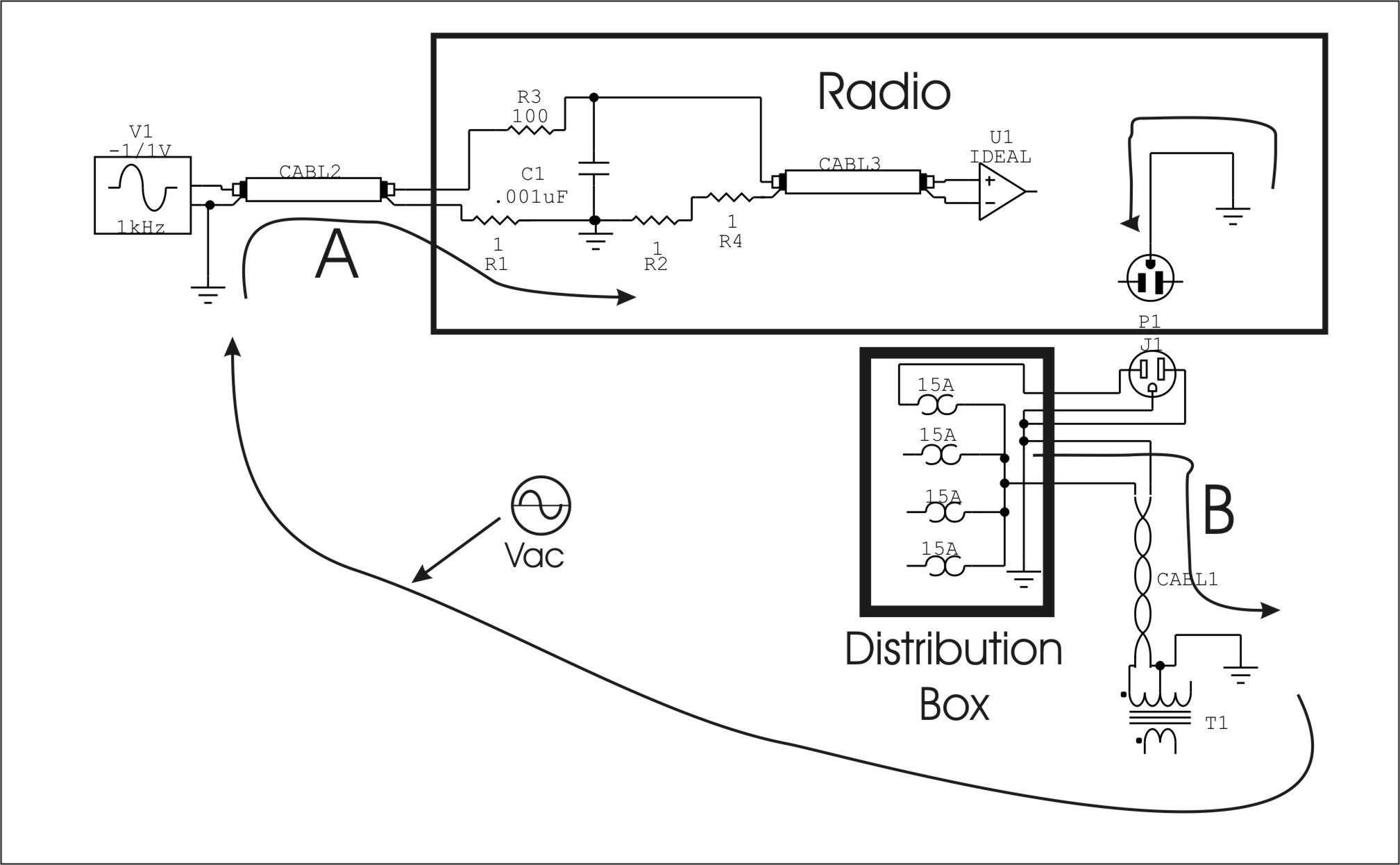
Power
Line induced hum
Harmful ground loops
are caused by
grounding sensitive
leads or systems to
different points. In
this example current
returning to the
pole transformer
causes a voltage
drop along CABL1,
from the pole to the
house.
If we ground a low
level audio source,
like V1, to any
external ground some
AC current from the
mains neutral will
partially flow
through shield
resistance (R1) and
modulate source V1
with hum.
Vac represents the
AC loop caused by
voltage drop in the
power mains neutral
system.
The ONLY
correct place for an
audio ground is at
the microphone
connector entrance
to the shield
enclosure of the
radio. That ground
has to be virtually
zero resistance to
the cabinet. Nothing
else on the audio
line should be
grounded, unless it
is grounded to that
jack-to-chassis
connection.
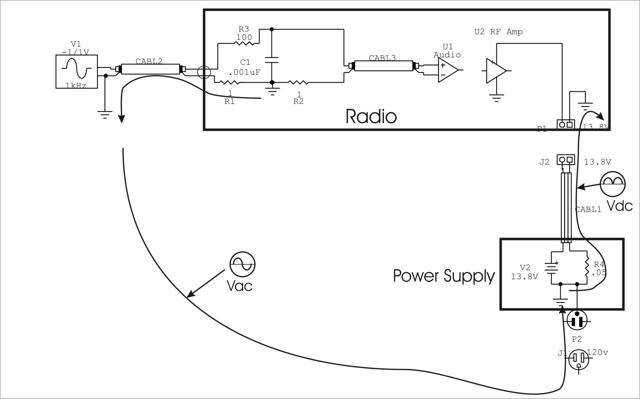
Radios using mains
powered 13.8 VDC
power supplies
suffer all the same
ill effects from
power mains hum,
plus they have a new
problem. The small
resistance (R4) of
the negative lead
allows the power
supply to modulate
audio lines at a
rate tied to the SSB
envelope. This
produces and audio
sound much like RFI
or SSB with a BFO
turned off. This
voltage is
represented by Vdc.
Again the fault
occurs because of
the extra
unnecessary ground
at the audio source
(V1).
Vac can occur along
with Vdc, and
usually does.
Once again the only
place the audio line
should be grounded
is at the entrance
to the radio
housing.
Computer to Radio
Interfaces
While we can on
occasion get lucky
and get away with
breaking good
engineering practice
rules, we should use
isolation
transformers on
audio lines. Many
trashy PSK signals
are created because
users don’t isolate
the grounds, and
often times this
trash is out of the
receiver’s bandpass. Because
the hum and noise is
off-frequency from
desired tones,
many problems go
unnoticed (except by
people up or down
the band who have
noise or hum pop on
their frequency when
someone up or down
the band transmits).
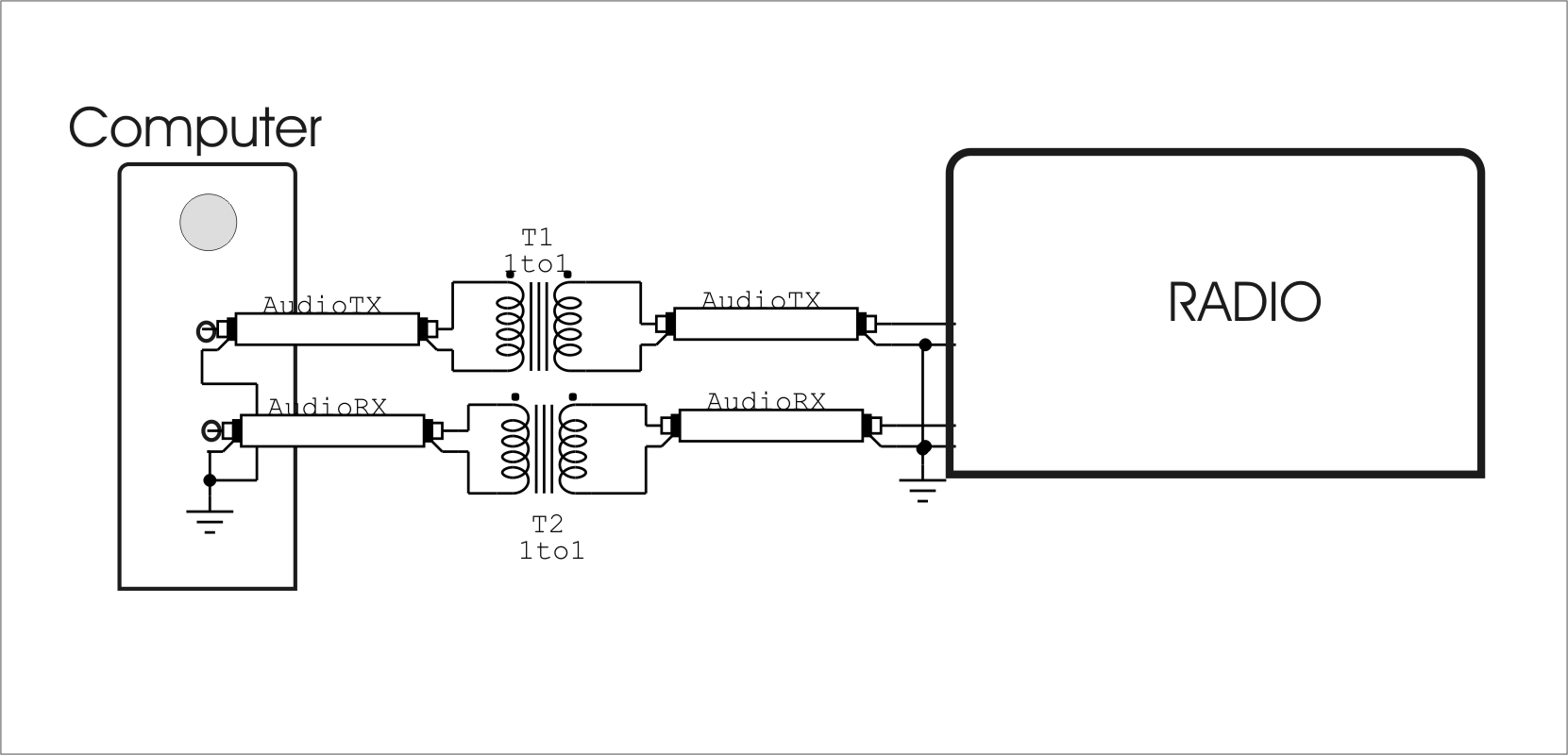
T1 and T2 isolate
the ground paths on
the computer and the
ground paths on the
radio cabinet or
chassis. Without T1
and T2 the
resistance of the
shields would drop
voltage, and that
voltage would
effectively be in
series with the
audio inputs and
outputs.
This can result in
hum, or the dc power
amplifier current of
a power amplifier
using an external
supply modulating
the audio system.
T1 and T2 can be
small audio
transformers of
150-1000 ohms
impedance.
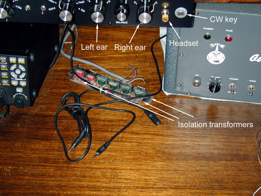
This is my house
operating desk audio
system. The
transformers are
normally behind the
radios out of sight.
Pay particular
attention to the
nylon insulator
system on my CW key
jack. This is to
prevent the CW
keyer, which
operates on 13.8
volts dc as well as
connecting to the
radio, from
grounding to the
headphone jack
ground. If I short
the key jack shell
to the metal panel
where audio lines
are “grounded”, hum
appears in the
headset.
The green audio line
transformers are
42TU013-RC They are
8-ohm CT to 1000-ohm
CT 1/2-watt
transistor output
transformers. I run
the radio speaker
audio output into
the full eight-ohm
winding. I use half
of the 1000-ohm
winding to drive the
audio switching and
buss system. The
audio buss (gray
cable) is terminated
in 47-ohm
resistors for each
of the four audio
channels.
The computer
interface connects
through the red
transformers, which
are 500:500 ohm
Xicon 42TU500
transformers.
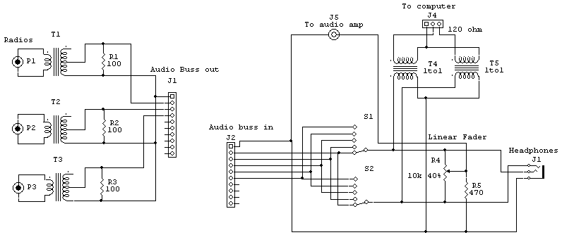
This is my basic headphone wiring in both my contest barn and house shack. It
can be built out to handle as many radios as necessary, and will interface in
stereo. It allows any radio to be on any ear, and multiple switch and jack units
can be bridged.
The buss in my contest barn covers 4 operating tables in stereo.
The left half of the schematic drives the audio
buss, the right half bridges the audio buss. With a low source impedance (like
the speaker output of a radio) driving the buss, plus the intentionally heavy
buss loading resistances R1 through R3(+), volume changes are minimal as
headphones are switched in or out on any given radio.
Special note on T1-T3(+) . As many transformers can
be added as the S1 and S2 will accommodate. The windings are center tapped. I
use the full 8-ohm winding for the input from radios, and only half of the
secondary to drive the audio buss. This makes the impedance ratio around 4 : 125
ohms. I load the secondary intentionally slightly heavy with no ill effects. The
extra winding impedance extends low frequency response and limits the highs
slightly, to slightly reduce hiss in headphones when using narrow CW filters.
|
Audio
transformer test
for you!
If I have an
1000-ohm CT
transformer and
I only use
one-half of the
winding, from
one end to the
center tap, what
is the new
winding
impedance?
Most people
intuitively
answer 500 ohms.
The impedance is
250 ohms! This
is because
impedance
changes by the
square of the
turns ratio. The
center tap to
one end is half
of the turns, so
it has 1/4th the
impedance.
An 8-ohm center
tapped winding
is not 4 ohms
each side of
center tap, it
is 2 ohms
each side of
center tap.
Double the turns
ratio and we
have four times
the impedance.
Halve it, and we
have 1/4 the
impedance.
|
More
on Transformer
Impedance
When a transformer
has too little
impedance low
frequency response
suffers. It also
saturates easier.
When the transformer
impedance is too
high, high frequency
response suffers.
It is the load that
determines the
“match” for
transformer
impedance, not the
source. If we want
a 600-ohm
transformer to be
flattest running
into a 10K ohm
radio input , we
should connect a
680-ohm resistor
across the secondary
(load) side going
into the radio. The
10,000 ohm radio can
then bridge directly across
the loaded
secondary. If we
needed to match the
10,000 ohms because
the input of the
radio is fussy
(this is normally
not an
issue when a high-Z
load bridges a low-Z
source) we could
use an L-pad. A
suitable L-pad would
be a 680 ohm
resistor to ground,
and a 10,000 ohm
series resistor to
the high impedance
load. Power loss
would be almost
20-dB.
As for the
transformer going to
the computer, most
computers should
have a line input
impedance or be
designed to bridge
the source without
issues so long as
the source Z is less
than load Z
presented by the
computer. If we
wanted to get fussy
we could load the
secondary and bridge
across it with the
computer.
I very rarely find
it necessary, unless
I want high fidelity
or maximum power
transfer, to worry
about getting an
optimum match. All
of my radios go into
an 8-ohm to 250-ohm
audio transformer
to drive the audio
busses in the shack.
This transformer is
an 8- to 1000-ohm
transformer, and
only use half of the
1000-ohm winding. There are separate
isolation
transformers on each
piece of gear at the
outputs, including
the computer.
Shields are ONLY
grounded at inputs.
Without
this I have audio
line noise and hum.
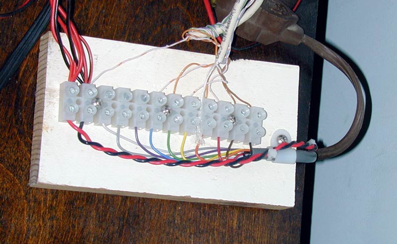
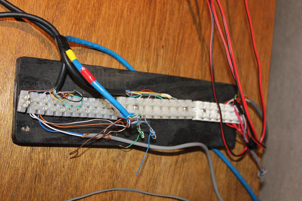
Wiring Blocks
To facilitate moving things around on my desks, I use movable wiring blocks.
This minimizes the number of individual wires or cables running all over the
room. In this example I have several power plugs connected to one supply line
(fused at the source). The CAT5 cables connected to other items on the shelf,
like antennas switches.
Every pin number, color code, and functions gets documented on a list!
Page Under Construction
RF Ingress and
Shields
Most shields
|