Coaxial feedlines, currents in feedlines and shielded wires
|
Coaxial line, shielded ground, and shielded wires |
|
|
Jump down to
Shielded Grounds
Using Coax
related pages at :
Concentric
Transmission Lines
(Coaxial Cable)
With a shield
more than several
skin depths thick
skin
depth
isolates the inner and outer wall of the shield. This barrier caused by
skin depth causes
coaxial cables,
single-wire shielded
cables, or
concentric lines
to become the electrical
equivalent of three-conductor concentric
transmission lines. A standard coaxial line in effect has the outside of the
shield, the inside of the shield, and the center conductor as three
electrically-separated or isolated conductors.
Electrical rules
require the center
conductor and inside
of the
shield to always
carry equal and
opposite RF
currents.
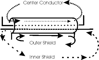
Notice in the
drawing above the
center and inside of
the shield carry
equal and opposite
direction RF
currents. This
ALWAYS is the case
when the shield is
several skin
depths
thick. We
cannot force
anything else to
happen!
In the drawing
above and below, the
outside of the
shield is isolated
by skin effect. It
behaves like a
separate
transmission outer
conductor. Skin
effect prevents any
current, voltage, or
field (even
magnetic) from
penetrating the
shield when the
shield is many skin
depths thick. Only
the breaks at the
ends connect the
inner and outer
shield conduction
layers.
The only egress
or ingress points
for voltage and
current are where
discontinuity in the
shield might occur
through an
intentional or
accidental break in
the shield.
Radiation In or
Out of Shielded
Lines
To operate
without radiation,
coaxial cables
require equal and
opposite currents in
the shield and the
center conductor.
The outside of the
shield must not have
an RF potential
difference along
it’s length. We
cannot have voltage
gradient
(electrical fields)
along the length or
the outer conductor
layer will conduct
currents. This
generally means
both ends of the
cable should have
zero volts to earth
or the environment
the cable operates
in.
A
unique
characteristic of RF
current is it always
moves away from the
densest magnetic
field. This is the
same thing that
causes
skin effect.
Why
then does current
flow inside some
cables, like
transmission lines?
Because the center
conductor and shield
carry opposing
currents!
When
the current flowing
from C to D equals
current flowing from
B to A, the magnetic
and electric fields
from the center
conductor “pull” all
current to the
inside of the
shield. As long as
the shield is
several skin depths
thick, all current
stays inside the
shield. The skin of
the shield for all
practical purposes
is an insulator or
isolator for all
currents, just as my
skin depth page
shows.
Moving all current
to the inner wall
and shielding the
cable, always
requires opposing
flow of exactly
equal currents.
Any
additional current,
beyond the
subtraction of
center and shield
currents, moves to
the
outside
of the shield.
If we feed
exactly equal and
opposite currents
into the coax ends,
currents have no
choice but to flow INSIDE
the cable shield!
The outermost
conductor can be
treated as a single
wire, since
everything else is
“hidden
inside”. When
currents are equal
and opposite on the
shield and center, “extra”
current that flows over
the outside of the
shield cannot exist. Because of
this rule, we do not
need to ground the
shield to prevent
radiation. The trick
here is we need to
have equal and
opposite currents.
When the shield has
potential difference
along the length we
can greatly reduce
outside currents by
making the outside
of the coax have a
high impedance. We
can do this by
selecting a proper
cable length, by
adding sleeves of
soft-iron magnetic
materials or winding
the cable in a coil
with or without a
core to form a
choke. Skin
depth prevents the
inside of the cable
from
“seeing”
what is done on the
outside.
Most
interesting in all
of this is the claim
or idea the
“shield”
of a shielded
loop allows
magnetic fields to
pass while filtering
electric fields. The
same rules apply as
with coaxial lines.
The shield actually
becomes the antenna,
and it couples to
the inside only at
shield gaps. If the
gaps aren’t exactly
opposite the
grounded part of the
loop and inner
conductors don’t
exit exactly at that
grounded point, the
shield
actually
UNbalances the loop!
Coax
as a Shielded Ground
Lead or Radial
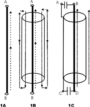
Assume 1 ampere of
RF current flows
1A
shows current in a
single
conductor. In
this example let’s
assume current is
one ampere. All
current flows
through the single
conductor, and the
conductor freely
radiates.
1B
shows current when
center conductor is
insulated and fed
with 1 ampere. In
this case ALL
currents are 1
ampere, but the
effective resistance
and reactance
of point A to
B increases! This
line radiates just
as well as the line
in 1A, but impedance
and loss resistance
increases slightly.
1C
shows current when a
so-called
“shielded
ground” is
used. With low
reactance
capacitors, if A to
C conducts radio
frequency currents,
the current flowing
from B to D inside
the cable is
negligible.
The same
is true if B to D is
used as the
connection.
B to D have no
current. All RF current
is on the cable’s
outside wall. The RF
impedance is
essentially the
same as the shield
alone. The line
freely radiates
because, once again,
one ampere of
unopposed current
flows over the
outside shield wall.
If
in 1C the capacitors
are removed and the
center conductor
alone from C to D
conducts RF
current, the inside
of the shield and
the inner conductor
between B and D will
have no RF current.
The impedance is the
same as the shield
alone. The line once
again freely
radiates.
It is
electrically
impossible to shield
a ground lead. This is because current can only flow inside a coaxial
cable when the center and shield carry opposite
flowing currents. Same direction currents, like ground currents from the station
to ground, can never flow inside any conductor or group of conductors. Common
mode currents always flow with most current in the area the greatest distance
away from the center.
This
same effect also occurs
when coax is
used as a radial or
as an antenna. This is an electrical law that cannot be
circumvented or broken.
So we again see, despite claims in a few articles about antennas and
radials, velocity
factor inside the
cable does not
in the least affect electrical
length of the
radial or antenna!!
Pointing out how it works may bring forth a response “I added a
shield ground and it cured my RFI problems”. In fact they never added a shielded
ground! They really just altered the ground they had, generally making it much
thicker and often a different length. Through sheer accident they changed the
ground connection in a way that produced a voltage null in the shack, and
attributed the lucky accident to something impossible to do. They changed one
thing thinking one thing, and through dumb luck wound up changing something
else. Then they used the accident to invent or support an impossible claim.
Everyone already knows, or should know, wider ground leads make
better grounds! It isn’t the alleged “shielding” that helped. As a matter of
fact the capacitors and inside conductor could be dispensed with and not change
the system at radio frequencies one bit. What actually corrected the problem was
using a thicker ground lead, and maybe changing the length to a more favorable
length. Not only that, when the new shielded ground lead was run, most people
probably cleaned up all their other messy or poor connections.
Wider area ground leads make lower impedance RF ground. There is
no magic, and there is no such thing as a shielded ground.
since
Dec 2004