Common mode current
Common Mode Currents
Cleaning Up Problems and Impedance Required
jump to Common_Mode_Choke
Jump down this page
to dipole models
This page explains common mode currents. Currents flowing without equal closely spaced return currents
are called common mode currents. Common mode currents cause
conductors to couple to each other. Common mode currents are generally behind
desired EM
radiation and reception. Unwanted common mode currents can also flow through sensitive
equipment, causing RFI, or couple unwanted noise into a system from a noise
source.
We have to be realistic about goals. There has been
an alarming trend to specify unrealistic impedance for common mode choke.
In balanced lines, common mode current flows on both conductors. In balanced
lines, unbalanced current levels prove common mode.
Balanced currents do not prove the system is free of
common mode. Currents can
be equal in both conductors even with 100% common mode!
In coaxial cables with
shields more than several skin depths thick, common mode flows exclusively on
the outside layer of the shield. It is impossible to force common mode currents
to the inside of shields more than a few skin depths thick.
coaxial lines
and shielded wires
See Current Balance
Common
mode currents cause coupling between conductors as well as electromagnetic radiation
(transmitting or receiving). Common mode currents bring RF directly into the
operating position wiring, contributing to equipment interference problems.
Likewise if RF couples in, it also couples out to the antenna. This can increase
noise and interference to desired signals when receiving. Inside the Ham
shack or along the antenna feed line,
common mode currents are responsible for unwanted noise ingress, RFI, RF burns,
and a host of other maladies. Common mode currents effectively bring the radiating
part of the antenna system down along the feed line or the antenna’s metallic
supporting structure. Common mode currents can extend all the way to the desk
and station equipment, and even out through power line connections. Problems
flow both ways.
Common mode currents also serve a useful function. In any antenna, common mode currents in the antenna
element(s) are responsible for radiation. From this standpoint we
cannot have radio communications without common mode. Every antenna has common mode current someplace, otherwise it would not radiate.
There
must be enough isolation between “good” system common mode and
undesired common mode to make the undesired effects unnoticeable.
The keyword is unnoticeable, since zero or a universal arbitrary specification
is not realistic. We generally do not want feedlines to noticeably act like
antennas, and we certainly don’t want electrical noises in
house wiring or surroundings to infiltrate the antenna. The best idea is to keep
significant or troublesome common mode current levels from our antenna systems out of
sensitive equipment, and reduce noise and unwanted signals making back to the
antenna, where they can override desired signals. Things seem to have gotten
beyond reason, once conducted signals fall below unavoidable space coupling,
further suppression is meaningless. Working systems also have impedance limits
far below test bench limits.
Proper feedline treatment also offers
improved lighting damage immunity. Common mode currents are generally best dealt with at the source or as close to the
source as practical without compromising effectiveness.
Most important of all, cures
are generally not a one-size-fits-all solution. The most effective cure and work
required is dependent
on the specific installation. To understand how a common mode suppressor or
choke works and the impedance required, we must
understand balance. We must further have a reasonable grasp of circuit analysis
and the imnpedance limits of lumped components at radio frequencies, and some
idea how things couple at a distance. I’ll do my best to describe these limits
without being complicated. I can design things that test to very high
impedances on a test bench, but they can have no practical use when connected to
long random cables.
Balanced and
Unbalanced Systems
Most often balance is described only by current in each
conductor of a transmission line. This is completely inadequate and can mislead
or confuse us. We cannot know balance without knowing voltage, current, and
phase.
Perfectly balanced lines and perfectly unbalanced
lines all have equal and opposite currents entering and leaving the conductors
at each end, as can lines that are out of balance. All properly operating
two-conductor transmission lines, coaxial or parallel wire, carry equal and
exactly opposite phase currents in the two conductors. Non-radiating coaxial
lines and parallel lines (twin lead or ladder line) both have exactly equal and
opposite flowing currents entering or leaving each conductor at any given end of
the transmission line. (See coaxial
lines at this link)
The only thing determining the gender of balance
is the electric field to space surround the line, or the conductor voltages to
“ground” or space around the line.
We can establish these rules for properly operating
transmission lines:
-
coaxial and balanced lines both have equal and opposite currents in
each conductor -
perfectly unbalanced lines have zero electrical
field (voltage) outside the line fringing to space, other objects, or to “ground” -
perfectly balanced lines have equal and opposite
electric fields fringing out to space around the line or coupling to “ground”.
These fields, for all practical purposes, vanish several conductor spacing’s
from the transmission line
Balanced Lines and Balanced Antennas
Dipoles and doublets are inherently balanced antennas. A relatively
symmetrical antenna installation will have very little common mode introduced by
the antenna, even if the antenna isn’t perfect. Problems can be created by the
antenna or feedline layout, but this usually demands a fairly significant
construction or layout error. Most balance problems, when using balanced feeders
on dipoles or doublets, are generated at the tuner or balun.
Non-symmetrical antennas, such as off center fed antennas or end fed antennas,
create severe common mode issues. The further the feeder is offset from center, the worse the
common mode issue. This means center fed doublets are least problematic,
off-center-fed antennas in between, and
end fed antennas are the worst possible common mode problems. As a matter of
fact, end fed antennas are 100% common mode at the feedpoint!
Coaxial Lines
Coaxial lines feeding less than perfectly unbalanced loads
are subject to common mode. Coaxial common mode currents, because of electrical
laws (look up Lenz’s law and descriptions of skin effect) appear on the shield’s outside
layer.
Anything inside the cable has to be differential mode!
There are two ways to significantly reduce or eliminate common mode. As one
solution, generally best at HF, we can install a
good current balun or common mode choke at the proper position along the
feedline. At VHF or even at upper HF in single band or odd harmonic operation,
with a
feedline spaced away from other things, we can simply ground the feedline shield
about 1/4λ
(or 3/4λ) from the floating balanced point.
Impedance Limits
RF systems have practical impedance limits. The impedance limits are
dependent on the operating frequency and physical size of the system. This
limits our choice of choke or balun design. It also limits our target
impedances.
While we can have fairly high impedances in small RF systems, melding extreme
test bench impedances into larger transmission line or antenna systems is an
exercise in futility. Let me do my best to give an example.
Let’s consider a one foot long one half inch diameter coaxial cable suspended
be vertically from a large sheet. The impedance of such conductor at 10 MHz in
somewhere in the -j 5,000 ohm range. Logically, in a real world system with
cables entering and leaving a choke or balun, we cannot have a useful series
impedance anywhere near that value. This would be especially true if the cable
were near other things, or longer. This problem also becomes worse with
increasing frequency, as well as with increasing physical size.
We can specify requirements that look good in a model or on paper, but are
unworkable or meaningless in real systems.
Cleaning Up Problems
Antenna design, layout, and wiring first.
Suppression last!
Some sites claim isolator or choking impedances of a few thousand ohms
or more are required to
isolate or eliminate
common mode currents. Systems requiring thousands of ohms to
mitigate common problems generally have a major
design, grounding, equipment, or layout problem(s).
In general, a properly constructed layout and proper
antenna with good connections and cabling will not benefit from suppression
inside the building. Even a severely compromised layout, such as those with
antenna’s close to RF sensitive devices and/or equipment in terms of wavelength, should
not be sensitive to RFI when good basic layout and wiring principles are
followed. There is a side benefit
to good station wiring and proper transmission line layouts. The
same things that reduce RF system common mode problems reduce lighting damage
susceptibility.
This is because most lighting damage is s caused by common mode current, making
lightning protection and RFI immunity go hand-in-hand.
Once
the station or equipment is properly installed, even relatively small amounts of
additional common mode impedance will offer a significant reduction in common
mode. A proper system will not need more than a few dozen ohms or hundred ohms
additional isolation. A poor layout might not be improved with nearly infinite
isolating impedance. One thing is universally sure, if a system needs more than
a few hundred ohms CM suppression the system has a major layout or wiring
problem. It is best to fix that problem before adding
chokes, and worrying about obtaining choke impedances
impossible to achieve and maintain in a real-world system is pointless.
Place impedances in perspective. On 40 meters, 9 pF of stray capacitance is
2500 ohms. Do we really honestly think a few feet of wire would have less
than 25-100 pF of stray capacitance coupling to other things?
Anyone can make an isolator or choke produce a very large number in an uncluttered,
controlled, test bench setup. But in the real world we have cables and wires of
significant length laying in and around our desk equipment, and that changes
things quite a bit. The real world is different than a zero lead length
test bench setup. Choke or isolation impedances in the thousands of ohms are
possible and practical in controlled layouts or environments, like at a
feedpoint dangling in space. On a desk or near other large conductive objects
like cables near booms or towers, more than a few hundred ohms isolation
is difficult.
In most cases a combination of grounding along with very modest common mode
impedance is best. In many cases when can have high isolation just with
grounding alone, but grounding and cabling has to be proper!
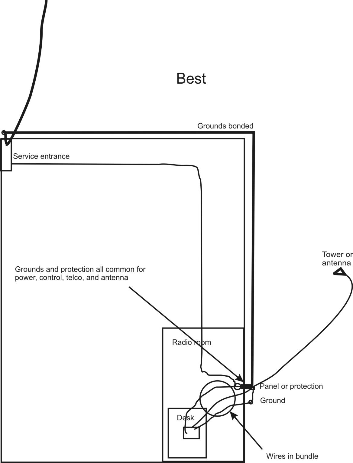
Proper Layout
All proper installation should have a common point where cables enter for all
desk functions, including power, Internet, control, and RF cables.
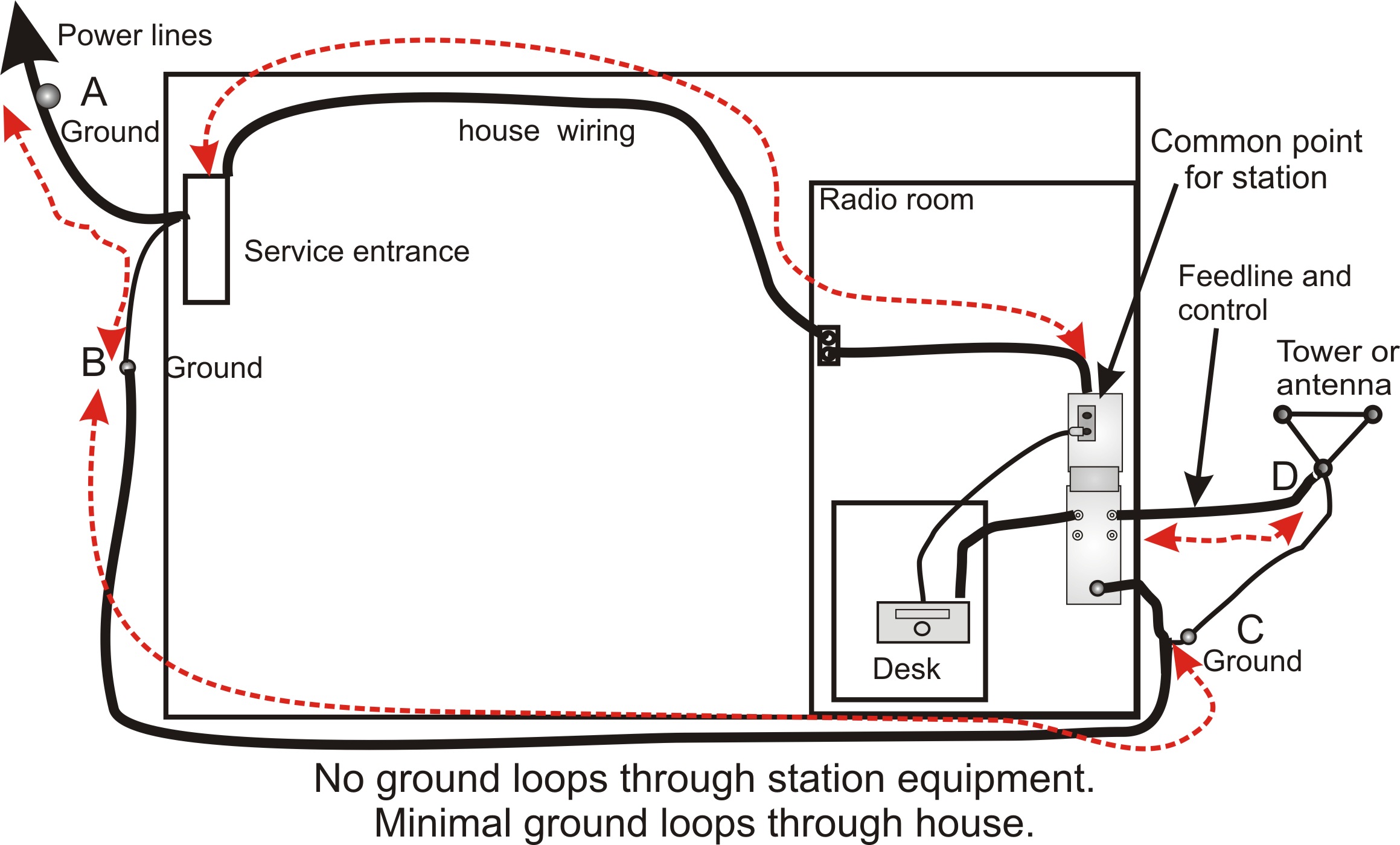
Shack and power mains grounds must be bonded with fairly low impedance, the
lower the bonding impedance better.
Multiple isolated grounds create
dangerous ground path loops, inviting damage or RFI problems.
Cables to the desk should be bundled and/or routed in
parallel. Bundling or close parallel routing reduces “open area” of the loop
formed by multiple conductors.
What Does a Common
Mode Choke Do?
A common mode choke alters the common mode impedance of the system. The
isolation added to any system, just like the impedance required, is not predictable.
Isolation can only be measured with a great
deal of work. We can say one thing with some certainty, large values of common
mode impedance are rarely necessary.
Attenuation with the addition of a choke is a function of
the common mode source impedance, the common mode line impedance on both sides
of the choke, and the impedance of the line’s ground at the equipment side. This
is not a simple system. Common mode source and termination impedances are
virtually never anywhere around
the 50-ohms a typical S21 or S12 measurements are made with. Because of this,.
measured or advertised attenuations are meaningless numbers and any blanket prediction of system
choke impedance needs are pretty much useless. All that can be said is it is
best to use a dissipative impedance (Q<1) rather than reactive (Q>>1) in RFI
suppressor systems.
In “A” below, a transmitter drives the coaxial feedline in
differential (push-pull). The center conductor in this example A’s 50-watt
transmitter, assuming matched lines, will be at 50 volts. The shield is ideally
at 0 volts to earth, being a commonly grounded point with earth. The current are
equal and opposite in properly operating balanced and unbalanced lines, but in
normal operation the shield being at zero volts to “ground” (or to the
chassis) defines the system as being a perfectly unbalanced system.
If the system were perfectly balanced transmission line currents would still
be equal and opposite. The transmitter voltages from each feeder conductor to
chassis or ground, however, would be equal and opposite in a balanced line
system. The line would also have two parallel conductors equally coupled to
earth or ground through space.
Coaxial line behavior, from skin effect and mutual coupling from the
shield’s inner wall to the center conductor, pulls all of the transmitter’s
differential current to the area inside shield wall. The voltage appearing at the antenna
drives the common mode impedances of both halves of a “balanced” antenna,
pushing one side of the antenna against the other antenna half.
A
halfwave dipole, depending on construction, height, and surroundings, has
essentially equal resistances. We’ll use the values shown as a discussion point.
If antenna current was one ampere and no common mode flowed on the coax, each
half of the antenna would have 25 volts to earth at the feedpoint. The
voltage developed across Rant2 causes the common mode problems, because that
voltage also excites the shield on the shield outside.
Allowing that voltage to “float”, in this example to 25V, is the same as
preventing unwanted outside shield current from developing.
If Rant2 below
was near zero ohms, it would be a unbalanced antenna with a very good ground.
The better the ground, the lower “Rant2” below, the less voltage is in series with the
resistance driving the shield (B).
This system is complicated by antenna characteristics and other things. The
antenna system common mode impedance and grounding determines the source
impedance and voltage driving the shield with common mode.
The system is further complicated in that cable1’s length and surge impedance
modifies the voltage and impedance at the common mode choke. In its most simplified
form, the common mode choke system looks like a pi-attenuator. The common mode
source impedance at the antenna, as modified by the cable common mode surge impedance
and
shunting leakage and ground paths modifies voltage and impedance driving the
CMC (common mode choke).
Similarly, common mode impedance into the station
equipment, likely
a pretty low impedance, determines the station side load on the pi attenuator
formed with CMC.
The attenuation and required CMC impedance quite obviously can be all over the
place. While none of us can predict the real attenuation provided by a given CMC
or predict how much CMC impedance is “enough” and how much is a waste
of effort, we can make a pretty reasonable generalization. It is very safe to
say any system requiring CMC impedances beyond low hundred’s of ohms needs
layout, design, or re-wiring help more than some extraordinary impedance.
My station, where lowest possible noise floor is paramount, has never
required more than a 50-100 ohms of CMC to mitigate all traces of problems. I’ve
actually found grounding and good connections to be far more productive and
reliable than dependence on a higher CMC impedances. Once I get into
the dozens or hundreds of ohms without complete mitigation of noise, I know I
have a major problem with shield integrity. I look for the real problem.
Common Mode Currents, Baluns, and CM Chokes
To understand how a balun operates and why a balun is
needed, we must understand balance. We tend to think of balance only in the
amount of current in each conductor of a transmission line, but that thinking
can mislead or confuse us. Perfectly balanced lines and perfectly unbalanced
lines alike have equal and opposite currents entering and leaving the conductors
at each end!
Coaxial cables with shields more than several skin depths
thick always carry equal and opposite flowing currents on the inside of their
shields and their center conductors. Current direction and current ratio between
the center conductor and inside of the shield in a non-radiating coaxial line is
no different than currents in each conductor of a perfectly balanced ladder
line. In both unbalanced coaxial lines and balanced lines, the two conductors
making up the line carry equal and opposite flowing currents.
When currents flow without close-by opposing currents, we
call the unopposed portion of current common mode current. Common
mode currents promote or encourage external coupling and radiation. In a dipole
antenna, or any antenna for that matter, common mode currents in the antenna
element are responsible for radiation. In the hamshack or along a feed line,
common mode current is responsible for unwanted noise ingress, RFI, RF burns,
and a host of other maladies. Common mode currents, in effect, bring the
radiating system into the feed line or station equipment.
Common-mode currents, or currents flowing in the same
direction, cannot exist inside a coaxial cable at any frequency
where the shield is several skin depths thick. Shield skin depth serves to
isolate the inside of the shield from the outer wall of the shield. Common mode
(same direction) currents can only flow on the outside of the coaxial cable
shield. Differential mode currents, or normal transmission line currents, flow
on the inner surface of the shield wall. Currents entering and leaving the
shield and center conductor at each end of a coaxial line must be equal and
opposite or the cable will radiate. If a coaxial line is not radiating, currents
in the shield and center conductor are exactly balanced and opposite flowing.
Both types of transmission lines, balanced and unbalanced, will have equal and
opposite currents entering and leaving each conductor when they have minimal
radiation.
What then defines an unbalanced line, source, or load? The
answer lies in the voltage or electrical potential between line conductors and
the environment around the line. In the ideal balanced line, the electric
potential of each conductor is equal and opposite in relationship to the
environment surrounding the line including the chassis or cabinets of our
equipment. In the ideal coaxial line, the outside of the shield has no
electrical potential difference to the environment around the line, including
the chassis or cabinets of our equipment. The shield of our coaxial cables, as
we commonly accept and understand, is at ground potential. We say the shield is
grounded.
With real-world antennas, the coaxial shield connection
point almost never has zero electrical potential to the environment around the
shield or points further along the cables length. Being a less-than-ideal
zero-voltage termination, shields almost always have common mode current, even
if a small percentage of differential (normal transmission line mode) current.
For example, the four radials of a groundplane antenna, no matter how configured
or tuned, are never truly at the same electrical potential as the environment
around the antenna or shield potential further down the feed line. Experimenting
with a groundplane antenna, we find the feedpoint is mostly but not perfectly
unbalanced. The shield is not connected to an electrically zero point.
Significant current can and often does excite the outside of the shield on a
groundplane antenna, with outside shield current 20% or more of antenna base
current under some feed line grounding and lengths! We consider the groundplane
antenna unbalanced and it is definitely not balanced, but it is not perfectly
unbalanced.
A coax fed dipole, or a vertical with a single radial, is
much worse for voltage balance. Because both antenna halves have finite and
nearly equal common mode impedances, both sides of the feedpoint want to have
nearly equal voltages between themselves and the environment around the
feedpoint. If we could magically make a perfect single point ground appear at
the feedpoint, both legs of these antennas would have very similar voltages to
that reference point. Of course we cant make that perfect reference point
appear, but the feed line brings a ground or reference connection to the
feedpoint. Third path impedance (the unwanted common mode path impedance) varies
with feed line length and routing, the environment the feed line routes through,
and how that feed line is grounded. While it can affect SWR and the current
flowing in that path be affected by SWR, high SWR does not cause and low SWR
does not prevent unwanted common mode current or RF in the shack.
Most antennas are neither perfectly balanced nor perfectly
unbalanced. Most antennas are in a nether-world someplace between perfectly
balanced and perfectly unbalanced. This is why a current balun, a device that
floats each balanced terminal to the voltage necessary to drive balanced
currents into the load, is such a desirable type of transmission line to antenna
interface.
Feedlines and Balance
Traditional
two-conductor
feedlines or
transmission lines
should have very
little, if any,
radiation. Typical coaxial
lines shouldn’t have noticeable
unwanted signals or noises
leaking into the
cable, and there
shouldn’t be
noticeable radiation
out of cables.
This is true at all radio frequencies from the AM broadcast band upward through
UHF, and applies to any cable with a reasonably thick single or double shield. Even
cheap 80% coverage shields are adequate throughout HF in all but the most
critical applications.
With unshielded
two-conductor
balanced lines,
some
small amount of
radiation from the line, or
leakage into the
line, exists. The leakage
amount should be
very low in properly installed
two-wire balanced
lines. Problems can occur with an unwanted EMI
source, or sensitive systems,
close to the
feed line. Problems with unwanted signal pickup or radiation can also occur with
very long open wire or unshielded balanced lines.
Ladder lines and
unshielded balanced RF lines should be isolated from other objects. Ideally, the
only air should be allowed within several conductor spacings of balanced
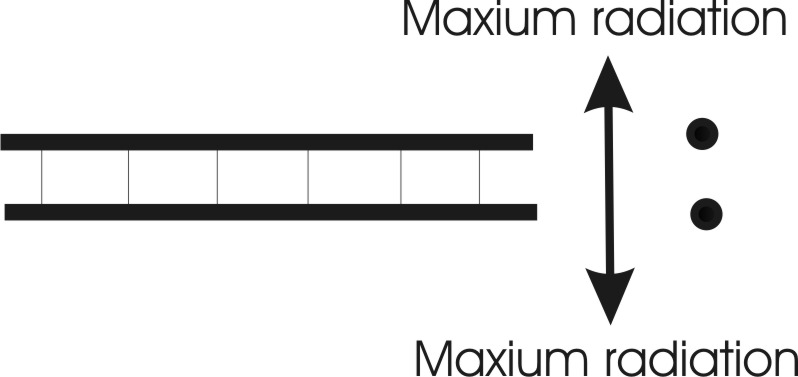
or unshielded lines. Significant levels of electric and
magnetic induction
fields surround the
line for distances of several transmission line conductor spacings. Line radiation
(electromagnetic radiation is a different mechanism) also extends out in a line
through the conductors. Unwanted radiation
primarily occurs
in directions aligned with the plane of the line conductors, nulling at right
angles to that plane.
Even with perfect balance in a two-conductor unshielded line, some radiation occurs. The
small spatial
separation prevents perfect cancellation of far field radiation. The
conductors carrying
out-of-phase
currents are not
occupying the same
physical space, causing a very small spatial phase delay. This means in two
directions radiation fields are not precisely 180 degrees out-of-phase. The
amount of phase error, and thus the level of radiation, is a function of
conductor spacing in wavelengths and the direction from the line. This
effect is minimized
by twisting the feed line at small
fractions of a
wavelength.
Radiation from a
perfectly terminated
six-inch spaced
50-foot long
two-wire
transmission line on
80 meters.
Radiation of the
same line at 30 MHz
is 24 dB stronger.
This is because the
conductor spacing in
wavelengths is
wider.
In order to be
balanced, a balanced
transmission line
must have both equal
and opposite
voltages at any
particular point
along the line as
well as equal and
exactly opposite
currents at any
particular point
along the line. If
the voltage
is not equal and
opposite, current
cannot remain equal
and opposite along
the balanced
transmission line.
This will result in
a very large
increase in feed line
radiation because
the imperfection
causes common mode
currents.
In order to be
unbalanced, an
unbalanced
transmission line
must have equal and
exactly opposite
currents entering
and leaving at every
point along the
line. The voltage
gradient laterally
along the outside of the transmission line has
to be zero. If
either the lateral
voltage gradient is
not zero, or currents entering the line are not equal and opposite on the shield
and center, current will not remain zero on the outside of the shield. This will
result in common-mode
shield currents and feed line radiation.
To
avoid feed line
radiation every
balanced to
unbalanced
transition has to be
properly treated for
level and phase of
voltage and
current.
To be properly balanced, the following must occur:
Voltages from 1 to A, and from 2 to A, must be equal and
opposite
Currents into 1 and 2, at the source, must be equal and
opposite
Voltages from 1 to C, and from 2 to C, at the load must
be equal and opposite
Currents out of 1 and 2, at the load, must be equal and
opposite
Voltages all along the line, at any
point, to B must be equal and opposite
Common Mode
Excitation
Common-mode
current is current
that is not opposed
or counteracted by
an equal and
opposite phase
current flowing
at every point along
the line in closely-spaced conductor or
conductors, and the
outside of the
shield has current
flowing in a coaxial
line.
Any
transmission line
becomes at least
partly, a
radiating conductor
if we make a poor
balanced to
unbalanced
transition.
This can be useful
when we wish to use
a feed line as an
antenna or as a
conventional
conductor, but it
can be detrimental
to a system if we do
not want radiation
or reception by our
feed lines. When we
excite a cable as
shown below, we have common
mode current:
The common mode source is
end-to-end on one or
more conductors of
twinlead
The common mode source is
end-to-end on one or
more conductors in a
twisted pair of
wires
The common mode source is
end-to-end on the
center, the shield,
or both conductors
in
coaxial
or shielded cables.
When we excite
a transmission line
as shown below we create
common-mode current:
The shielded coaxial
cable (top) and the
parallel conductor cable
(bottom) in this
diagram radiates
just like a single
wire would do.
Objects surrounding the line,
like dielectrics or
other conductors,
couple to or
interact with these lines
when they are fed or
excited this way.
For example, adding a ferrite
sleeve over the
lines will add loss
and/or make the lines
behave differently.
The impedance of the
system will change,
and if we are
watching system SWR
the SWR will change.
This is true even
when currents are
equal in the two
conductors, and can
even be true when
currents are equal
and opposite at one point in the system, so long
as the line is
excited this way.
The key to having
a line behave like a
transmission line is
feeding it
differentially
(across the two
conductors) at
one end, having a
load that maintains
the differential
excitation, and not
applying a voltage
or a potential
difference
across the length of
one or both
conductors.
This is a
transmission line as
we generally know
it, and as dozens of
reputable
engineering
textbooks define it:
This is
differential mode,
or TEM mode. This is
the normally desired
excitation mode when
a two-wire line
behaves like a
normal non-radiating
line that transfers
energy from one
point to another.
The above
configuration shows
a direct wire
connection from
source to load. It
transfers
voltage, current, or
impedance directly
along the conductors.
Dipoles and
Common Mode
1/8 wave high dipole
A
1/8th wave long
(35 feet in this
case) coaxial feed line
to the ground point
on a dipole often does not need a
balun! Here are
feeder common mode
currents for this
case:
| location | amperes |
| Left leg | 0.953 |
| source | 1.000 |
| Right leg | 1.001 |
| 1 ft | 0.052 |
| 2 | 0.054 |
| 3 | 0.056 |
| 4 | 0.057 |
| 5 | 0.058 |
| 6 | 0.060 |
| 7 | 0.061 |
| 8 | 0.062 |
| 9 | 0.064 |
| 10 | 0.065 |
| 11 | 0.066 |
| 12 | 0.067 |
| 13 | 0.068 |
| 14 | 0.069 |
| 15 | 0.070 |
| 16 | 0.071 |
| 17 | 0.072 |
| 18 | 0.073 |
| 19 | 0.073 |
| 20 | 0.074 |
| 21 | 0.075 |
| 22 | 0.075 |
| 23 | 0.076 |
| 24 | 0.077 |
| 25 | 0.077 |
| 26 | 0.078 |
| 27 | 0.078 |
| 28 | 0.078 |
| 29 | 0.079 |
| 30 | 0.079 |
| 31 | 0.079 |
| 32 | 0.079 |
| 33 | 0.079 |
| 34 | 0.079 |
| 35 ft | 0.079 |
Maximum feeder
common mode is only
.079 amperes (out of a 1 ampere source current) with
very good antenna
current balance. This is without any balun!
The same dipole 1/4 wave high:
| location | amperes |
| left side |