Common-Mode Noise
Related articles at
Balun Test
contains model of “perfect” dipole currents.
Sleeve Balun
shows how a sleeve adds impedance, useful for VHF and higher baluns
Receiving Common Mode
Noise shows how lack of a balun can contribute to system noise (it applies
to transmitting antennas as well)
Longwires, Verticals,
and Baluns shows how unbalanced antennas can have similar problems
Balun and Core selection
for transformers and baluns
Transmitting baluns
on testing transmitting baluns
Feedline Common Mode Isolation
Common-mode currents can be detrimental to antenna system efficiency, noise
or unwanted signal ingress, and/or
pattern. Common mode currents:
- in verticals or in end fed horizontal antennas with sparse counterpoise systems negatively impact
system efficiency - in all transmitting antennas can cause or increase local RFI
- when receiving, if noise currents somehow “leak” into the feedline, can increase noise floor
- can alter antenna pattern, especially degrading or modifying in
nulls
Not all common mode currents are noticeable, not all are bad. End fed
antennas without ground systems actually depend on feedline common mode to
function! If an end fed with a counterpoise had no common mode on the feeder,
they would not work at all!
Impedance Requirements
Recent articles have grossly exaggerated the impedance requirements for
common mode chokes. I understand why this happened. Those among us familiar with
audio systems are accustomed to lines of minuscule or negligable
wavelengths. A 20-foot cable is just 49200/20 = 0.0004 wavelengths long on 20
kHz. That same cable is 1/4 wave long on 10 MHz! There is a world of
difference in common mode behavior, especially common mode impedance!
A
second issue is stray capacitance. A very small stray capacitance of just
20 pF is 800 ohms on 10 MHz. It does absolutely no good to have tens of
thousands ohms choking impedance when the stray capacitance to surroundings or
across the choking device is hundreds of ohms.
Also, audio systems
outside of shot noise or thermal noises are dead quiet. We do not couple audio
lines to large antennas, where the antenna itself injects significant noise.
The analogy of an antenna in the world of audio would be a a microphone in a
noisy environment, with a cord around 4 miles long. We can’t possibly use more
than hundreds of ohms of suppression because, at radiao frequencies, we could
never notice any advantage from extreme impedances.
Outside of very specific cases common mode chokes or common mode isolation
devices, including current baluns, do not have to be extreme impedances.
Impedance required varies from a few dozen ohms to a few thousand ohms,
depending on application. As in any design application we should apply good
engineering along with common sense. A feedpoint might require several times the
feed impedance to adequately choke off common mode, while a downstream isolation
of a few dozen or a few hundred ohms might be adequate for other problems.
Using a simple dipole feedpoint as an example, each half has a common
mode impedance of half the net feedpoint impedance, or about 30 ohms. The
circuit appears like this:
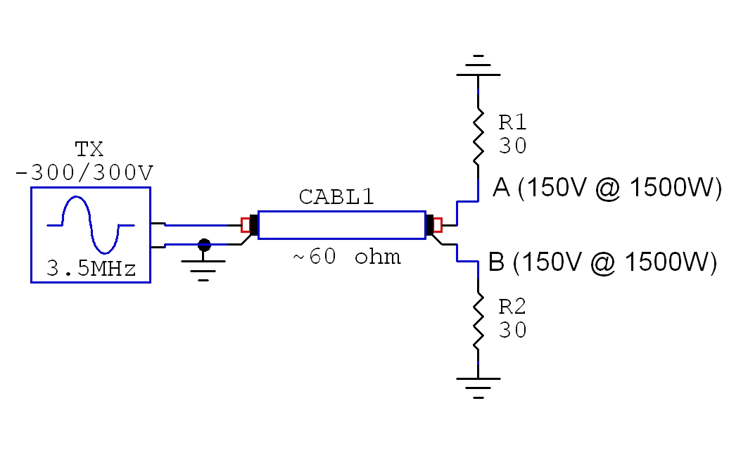
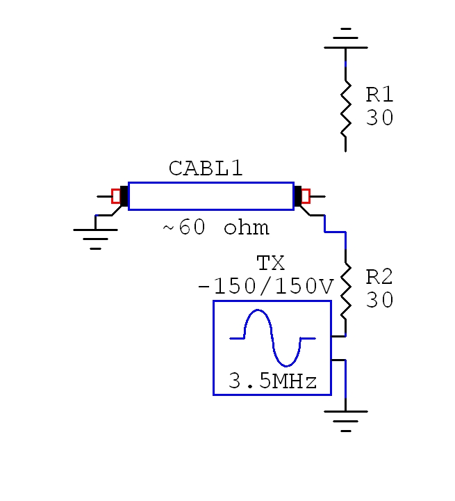
Using typical middle of road impedances (real world dipoles can range from
below 50 ohms to over 75 ohms), we find 1500 watts drives the shield with about
150 volts from a siource impedance of 30 ohms when the antenna is perfectly
balanced. The equivalent source driving the shield in a perfectly balanced
antenna appears as:
If the shield common mode Z is zero ohms, the dipole will force all of the
shield back onto the shield. None of the dipole current would flow into that
leg. The dipole would be perfectly unbalanced, and act like a Marconi with 30
ohm feed impedance. The shield current would be 7.07 amperes. Assuming the
antenna is balanced, a 1000 ohm common mode impedance would allow about .15
amperes to flow, or about 5% of antenna current.
We need considerably less than 1000 ohms for
most applications using verticals.
Transmitting
Transmitting antennas, especially when using low power
transmitters, are generally less critical for feed line isolation. Unless
impedance at the insertion point is high, modest values of choking impedance are
generally acceptable. Transmitting
antennas, when used for receiving, are less worrisome for common mode. This is
because antenna-mode signal levels at the feedpoint are generally very strong.
Efficient transmitting antennas produce high signal and noise
levels at the feedpoint. The strong signals often swamp out or override feed line
conducted common mode, except in
antenna pattern nulls. Unless common mode noise or signals are exceptionally
strong, the main problems with transmitting antennas appear in pattern null
areas, or appear as unnecessary RFI or loss of efficiency.
By including feed lines in models, we can
see how common mode currents skew or alter radiation patterns. We can also get
an idea of system common mode current levels.
If common mode currents are significant enough to alter patterns,
common mode currents
can also transfer unwanted
signals and noise into our transmitting antennas when receiving.
This is especially true with unfixable strong local noise sources. (If noise is
strong but removable at the source, it should be removed at the source.)
Some antennas are inherently troublesome designs. Some small antennas
typically perform beyond expectation for very short “antenna” length. This is
because strong electric fields near the antenna excite the feed line with
significant common mode currents, causing the feeder to radiate. Four compact antennas highly susceptible to feed line radiation
are Isotron, TAK-tenna, CFA, and
EH antennas. If those names are searched and
theoretical descriptions read, we find the “inventors” or proponents attribute
unexpected performance to some fictitious electromagnetic theory, such as
increased surface area or a specially phased mixing of induction (energy
storage) fields, rather than the true reason for
radiation.
Lessons are learned by studying compact transmitting antennas, which have
misled inventors and theorists into thinking they have discovered some physical
or electrical magic. feed line radiation can be a major issue in electrically
short antennas. Electrically short antennas unavoidably produce significant
energy storage fields, both magnetic and electric. The very strong localized electric field near the
feed line has the ability to couple significant energy into the feed line in the
form of common mode excitation. Another recent example appearing in Antennex’s compact antenna
articles was a thick stub “vertical” with no counterpoise. You
can find an example on the baluns
and verticals page of how poor or ineffective some counterpoise or Marconi
transmitting antenna ground systems can be. If feed line common-mode currents are
suppressed or eliminated, many compact radiators become significantly less
effective as radiators.
Some transmitting antennas actually function because of intentionally created
common mode currents. Examples are found in textbooks, such as the “Antenna Engineering
Handbook” by Jasik on and around page 22-6.
The antennas below, copied from Jasik’s textbook, outline the
derivation of a skirt collinear antenna from a simple feed line with the open end
terminated by a “stinger”.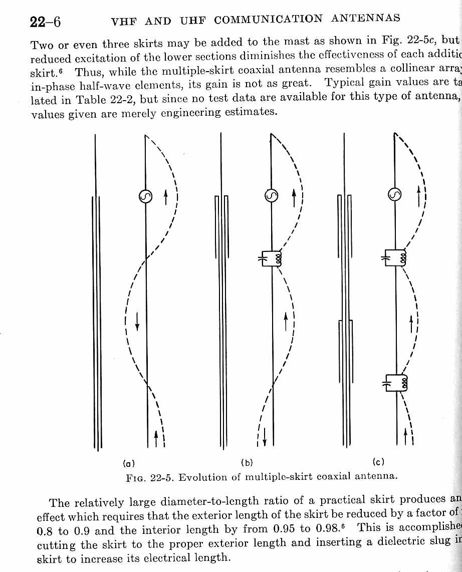
The center conductor termination in these drawings could easily be a ground rod
(in the case of a Snake) or an antenna like a Beverage or loop. The termination does not have to be an “open circuit”
1/4 wl stinger that intentionally radiates!
Looking at (a), we find by hanging any low impedance on the end of a coaxial
cable the shield is excited by common-mode current.
The
electrical equivalent is just as if the transmitter or receiver (generator
symbol in the drawings) is located at the end of the shield. This causes the outside of the shield
to act like a longwire antenna.
Unless the coaxial shield
connects to a zero impedance ground, current with flow on the shield. Looking at (c), we find even multiple sleeves appearing
as parallel tuned high-impedance circuits do not fully decouple a shield! It
takes grounding and series impedance to do a good job.
Analyzing our antennas, we often forget grounds are not perfect. We make
assumptions that four radials, or worse yet two radials, form a perfect
groundplane. Even a ground plane antenna many wavelengths from earth with four
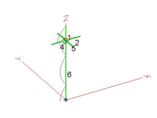
radials has considerable common-mode currents on the feed line. Consider the
following model of a “perfect” Ten Meter groundplane using four
perfectly horizontal 1/4 wl radials spaced every 90-degrees with a 1/4 wl
feed line hanging vertically and attached to the radials. The main element
current was set at 100.
EZNEC ver. 3.0
Groundplane 12/14/02 6:20:40 PM
————— CURRENT DATA —————
Frequency = 29.95 MHz.
Wire No. 1 Main Element 100
Radial
wires
19.71
feed line shield at
GP 69.96
1/4 wl from
GP
2.12
1/2 wl from
GP
71.3
3/4 wl from
GP .70557
At ground end of feed line 71
A glance at radial current shows the bulk of ampere-feet (ampere-feet, or
current over spatial distance, determines E-M radiation levels) is on the
feed line shield, not the antenna! Radiation from the feed line would be severe,
yet most amateur antenna designers claim with only four radials, or worse yet
two radials, no balun is needed! The claim that four radials makes a
“perfect ground” is false.
Why do we depend on a simple ground rod with 50 or more ohms RF resistance to
clamp a coaxial cable shield to ground?
Admittedly the above antenna is a worse-case example of feed line length and
grounding, but even better cases can cause problems. A better-case system
might be “nearly perfect” when transmitting (so far as efficiency and
pattern are concerned), but the system could be a
disaster receiving when significant amounts of conducted noise are present on the
station ground. With significant in-shack wiring noise, only the shunting impedance of ground
connections and feed line shield’s series impedance the prevent excessive
unwanted noise ingress at the antenna feedpoint.
Common Mode Currents and Receiving Antennas
A receiving example of an antenna that works because of common-mode
excitation is the “snake” antenna. The “snake antenna”, in order to receive
signals, intentionally induces common-mode on the coaxial cable shield. In
coaxial cables, current on the inside of the shield always flows opposite
current on the center conductor. With the center conductor grounded and the
shield floated, inner shield current makes the turn over the open shield end and
the inner shield current flows back over the cable’s shield outside. The entire
shield picks up signal, the snake is simply a reverse-fed random wire laid
directly on the ground.
Very small levels of conducted unwanted noise often go unnoticed in large
high-level transmitting antennas. This is because a large, efficient,
transmitting antenna has so much signal and noise level at the feedpoint that
the antenna’s signals and noise completely overwhelms any noise coupled in from
the antenna feed line or support. Noise ingress is a non-issue if local
noise levels on power lines are reasonably low, especially if the antenna has
significant common-mode
feed line rejection.
If a feed line is very long and lies directly on or is buried in the earth,
ground losses aid in attenuating conducted noise and unwanted common-mode signals. Unfortunately,
we almost never know if the feed line shield is contributing noise. We almost
never test or evaluate feed line common-mode signal contribution!
Measuring Common-Mode Noise
We sometimes hear we can test or evaluate a system for unwanted noise or
signal ingress by disconnecting
and replacing the antenna with a dummy load. This idea actually has
no theoretical foundation at all. Replacing an antenna with a small load
significantly alters common mode impedance of the system, and removes the
ingress point (the antenna’s feedpoint) entirely. Dummy load substitution
significantly changes system common-mode
impedance.
The only real test would come from a dummy load with the same connections and
impedances (both
differential and common mode) as the actual antenna. In other words the test
load has to be the actual antenna to keep feed line common mode ingress the same.
Obviously, casual dummy load substitution is a useless test!
The best approach is to use
preventative measures in initial system design and installation. Quite often the
cost of being safe is less than a few percent of the initial system expense.
Analyzing Systems
This circuit is simplification of typical common-mode paths in Beverage, EWE,
and other similar antenna systems. In this simplified case, since we only want
to develop a feel for series and shunt effect and how common mode gets into the
system, standing waves and reactances are ignored. The system below assumes a
compact system with pure resistances:
R_Source and V1 represent the source creating voltage across R_Station_Gnd,
the station’s ground impedance.
feed line_R is the equivalent series-impedance of the feed line shield.
Current through the feed line shield path develops a voltage across R_Ant_gnd,
which represents the earth connection ground impedance at the antenna.
V2 is a voltage source representing desired signals, while R_ant is an
impedance representing the sum of the coaxial differential input impedance
presented to the antenna (from the desired signal path into the coax) and the
actual antenna impedance.
Using the circuit below, we can find the attenuation. Assume:
R_source is 90-ohms
R_station_ gnd is 10 ohms
R3 (the coax shield) is 500 ohms
R5 is the combined series resistance of antenna impedance and impedance
presented by the feed line matching system, is 1000 ohms
In a typical system where a single six-foot or deeper rod (the earth’s skin
depth prevents deeper ground rods from decreasing resistance substantially) is
driven into typical soil, R_ANT_GND will typically be between 40 and 120
ohms, assume 100 ohms.
We have the following results:
Using the model above, only ~1 volt of common-mode voltage across the station
ground results in .152 volts driving the feed line exactly as a signal from
the antenna would. Path attenuation from station ground to the
feed line’s differential input at the antenna is 20log 151.5/985 or 16.26dB.
Changing the ground resistance to 10-ohms results in:
19.1/982.7 or ~34dB attenuation of common-mode noise.
Increasing R3 by adding beads has a similar effect. If R3 is effectively made
ten-times larger, attenuation is in the 30dB range.
Obviously it takes a combination of reducing ground resistance and/or adding series
impedance on the cable shield to significantly isolate any low-noise receiving
antenna from conducted ground noise over the feed line’s shield.
We sometimes observe much less noise on transmitting verticals after installing a large effective ground
system. Decreasing
ground impedance at the antenna reduces common-mode excitation of the
antenna feedpoint and reduces noise ingress, although adding a feed line
choke would sometimes help. There is no reason to go to
extremes in choke value, because a simple ground or two, or even a buried cable,
can multiply effects of any series impedance. Also, once the suppression system
takes common mode significantly below antenna signal levels, any additional
choke impedance is immeasurable and totally unobservable.
Solutions
A typical isolation scheme would be to use an isolated primary and secondary
in the matching transformer, and ground the feed line shield some distance away
from the antenna’s signal ground. This will introduce several thousand ohms of
reactance in the common-mode signal path, as well as provide another path to
earth for common-mode noise.
Another method, in cases where the feed line can not be isolated through a
floating primary in a matching transformer, is the use of multiple independent
ground rods with a series of choke baluns between each. This forms a
multi-section pi attenuator, making even modest choke impedances effective. As
an additional benefit, lightning paths are disrupted by this
method.
Summary
Noise contribution can vary with time. A receiving antenna’s ground
connection resistance varies with soil moisture, and sources of noise come and
go. As noise levels and grounding changes noise contribution as a
ratio to antenna noise will change. The fact we can not readily measure noise
contribution by substituting dummy loads further complicates the issue. Real
systems are vastly more complex than the simple analysis above.
Since we can’t easily measure noise contribution, we shouldn’t take chances.
It makes no sense to gamble that unwanted signals (from wrong directions) or noise
are so low that they will never contribute to noise in a special antenna installed
to reduce noise and interference.
While isolating feed line common mode effects from the antenna and antenna’s
ground may not reduce noise, isolation
can generally be achieved at virtually zero time and material cost. With the low
cost of prevention in
mind, it is shortsighted at best and foolish at worse to not isolate a feed line
shield from any low-noise antenna’s signal ground path.
Follow these rules for receiving antennas:
- With small magnetic loop antennas, make sure the antenna is properly
balanced - Lay feed lines directly on earth or bury feed lines in the soil so earth losses
reduce shield current and limit feed line common mode impedance - Be sure shield connections are properly made and snug
- If noise levels are high or antenna sensitivity is very low, isolate
the feed line from the antenna as it approaches the antenna by using choke
baluns - Ground the feed line a few dozen feet away from the antenna
- Avoid autotransformers. Instead use isolated primary and secondary
isolated winding transformers - Use an independent ground on the antenna. Never connect an antenna
signal ground to the
coaxial cable shield!