Delta loop
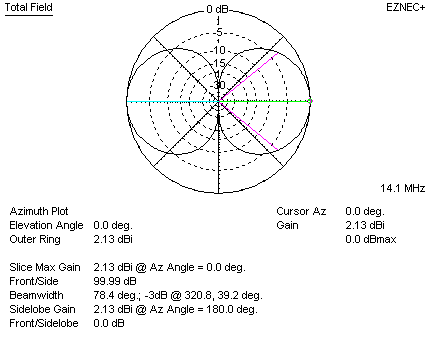
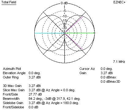
The cubical quad or quad loop is a square-shaped antenna. The gain of a
freespace dipole with typical negligible copper losses is 2.13 dBi. Freespace quad element isotropic
referenced gain is 3.27 dBi. Thus the quad
element has 3.27 – 2.13 = 1.14 dBd gain over the dipole. We call
this 1.14 dBd gain.
 Dipole
gain freespace
Quad element gain freespace:
The quad element is actually two stacked, shortened, bent dipoles
fed in phase. The fed dipole feeds power to the unfed half through the
attached ends. The square shape provides 1/4-wavelength broadside spacing between
the two short dipole’s current maxima. This more than offsets the immeasurable
gain decrease caused by bending the “dipole” antenna. The maximum possible gain
of a square quad element over a dipole at the same mean height is just over 1
dB. This peak gain difference occurs in freespace or at an optimum “sweet”
height. The “sweet” heights occurs where the dipole pattern has a strong broad
direct overhead lobe at heights around .75 wavelength. The quad has no gain over
a dipole, and actually can have loss, at heights where the dipole has a vertical
pattern null, such as 1/2 and 1 wavelength. The standard horizontally polarized
quad element is less effective than a dipole at mean heights below 1/2 wave.
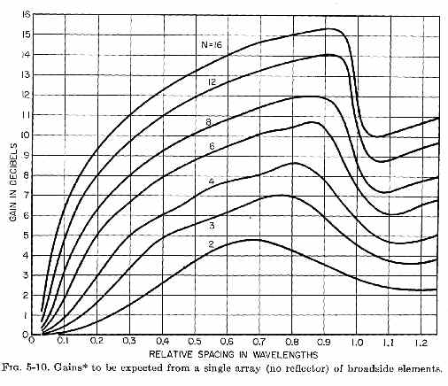
Stacking Gain Graph
From this we see gain of two current maximas spaced .25 wavelengths is about
1 dB over a single element by itself. This agrees with models.
Delta Loop
The delta loop is nothing more and nothing less than a reshaped quad element. The delta is pulled to a point at
one side, generally the apex. This either angles one of the high current area’s
angles to 120 degrees, which further reduces quad element gain, or it makes two
bends in high current areas (typically when vertically polarized).
Advantages
With a single apex point, the delta loop requires only one tall support. The
feedpoint, where the heavy coaxial line connects, can be placed at or near the delta loop
antenna bottom. The single tall support and low feed line connection point makes
delta loop construction and installation exceptionally simple and fast.
Disadvantages
Unfortunately, the delta has a pulled-in shape that reduces effective current
maxima area and current maxima spacing. The delta loop gives up some of the
quad’s 1 to 1.2 dB maximum possible gain over a dipole:
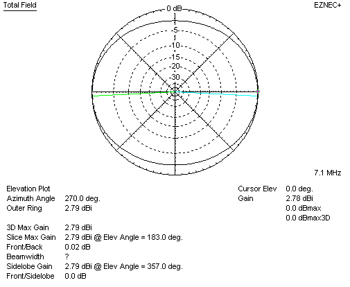
The delta loop has 2.78 dBi gain, which is 0.65 dBd gain, in freespace.
Freespace is the point of maximum delta gain advantage over a dipole at the same
mean height. That gain advantage is 0.65 dB.
The quad element, on the other hand, has 3.27 dBi gain, which is 1.14 dBd gain, in freespace.
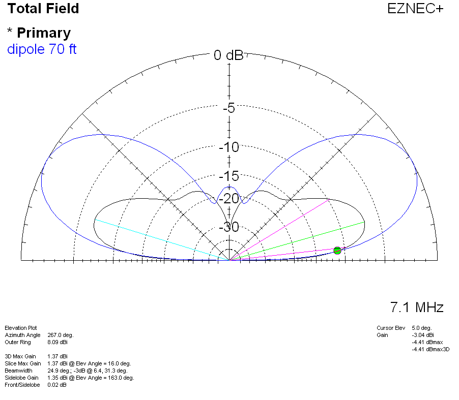
Delta Loop vs. Dipole Over Earth, with fixed support height
Let’s assume we have a typical 70-foot tower or trees, allowing a maximum
height of 70 feet over typical flat, clear, earth. A dipole and delta loop have
the following pattern and gain:
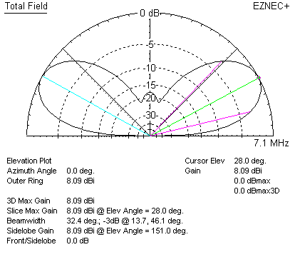
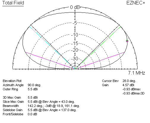
At 28 degrees elevation angle, the dipole has 8.09 dBi gain. At the same 28
degree elevation angle, the delta loop has 4.57 dBi gain. Even at delta
loop’s maximum
gain angle of 43 degrees, the delta loop has only 5.5 dBi gain.
- Compared to an inverted Vee dipole, or dipole, the delta loop lowers effective height of the antenna considerably,
increasing wave angle - The more compact area of the triangular-shaped full wave loop further reduces
the already small gain available from a full wave loop
Flattened Delta Loop
The Delta loop or quad loop effective operating height is really the mean
height of current maxima locations. With a 70-foot tall support, a delta or quad
loop’s antenna elevation pattern is one of much lower actual height. Often,
because height is limited, delta’s are installed in a “squashed” form. This
further reduces the maximum available gain of 0.65 dB over a dipole. The delta
starts to behave increasingly like a simple folded dipole as it is increasingly
squashed. It eventually becomes a folded dipole.
This is a delta squashed to 0.15 wavelength apex to base line height
difference. It has “horizontal polarization” (complimentary current maxima
in straight areas, apex feed) in freespace has about 0.1dBd gain:
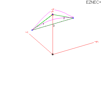
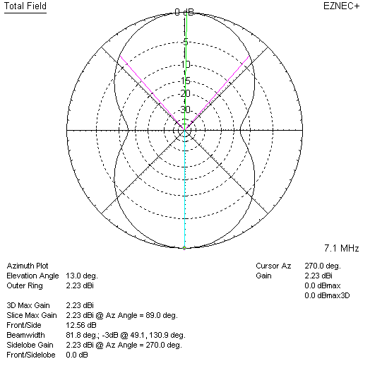
Vertically Polarized Delta Loop
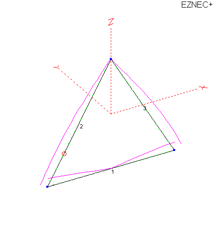
Feeding the Delta slightly up from the corner, around 1/4 of the side length
up, results in vertical polarization.
Note the current minimum is at the apex, and in the middle of the bottom.
The often used “corner feed” skews the current and polarizations.
Feeding the delta loop on a sloped wire about 25% up either side from a
bottom corner produces the
following vertically-polarized pattern:
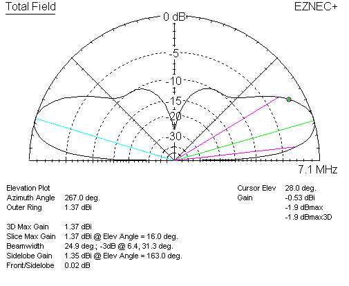
At 28 degrees elevation, the delta loop has -.53 dBi gain. This is -8.62 dBd
gain, or almost 9 dB weaker than a dipole.
At 16 degrees elevation, the vertically polarized delta has 1.37 dBi gain.
When compared to a horizontally polarized dipole at the same maximum height, the
delta has -4.72 dBd. Even at peak gain angle of the vertically polarized delta,
the
horizontally polarized dipole still has more gain.
The vertically polarized delta does not equal the dipole until around 5
degrees elevation angle.
Antennas radiate because of current over linear spatial distance. Antennas
obtain gain through proper spacing and phase of current maximums.
1.) When antennas are folded in a manner decreasing
current maximum spacing, or decreasing the linear (in line) spatial distance of
high current area, we reduce gain.
2.) When antennas are installed above earth, effective
antenna height is somewhere between peak height and minimum height of high
current areas.
3.) These effects apply to all antennas, and to arrays of
elements in more complex antennas.