Derale Fan Water Pump Controller
My new turbo system uses a sideways mounted
air-water-air intercooler system. I wanted a straight low-restriction air flow
path to the throttle body, so the intercooler sits on a platform just above the
water pump. I decided to eliminate the belt driven pump and fan in favor of an
electric pump and electric fan. I needed some way to control the electric water
pump and electric fan.
To minimize wear and tear on pumps and electric motors
and to minimize alternator load, I wanted to run my car’s water pump only as
fast as necessary. To prevent hot spots in the engine block or heads the water
has to circulate slowly during warm up. Mechanical pump cars normally use a
thermostat bypass hose to allow cold circulation. With an electric pump, I
decided to run the pump very slow during warm up and go full speed when the
engine reached desired operating temperature. This is the best way to do things
when not using a mechanical pump, thermostat, and bypass hose system.
An electric pump generally should not be run dead-headed into
a restriction. Running dead headed will increase motor current significantly.
This heats the motor and needlessly strains the vehicle’s electrical system.
Heat can damage the pump, the higher current wears down brushes faster. Using a
pulse width modulated controller will allow water to circulate slowly during
warm up and evenly warm the engine while also reducing battery load to just a
few amps. As the engine warms the PWM controller will step up motor speed,
running the motor just fast enough to maintain proper operating temperatures.
I bought several sample PWM controllers. I measured pulse
rate, peak current, average current, and electrical system noise. Some PWM
controllers were not even PWM!! Of all the controllers I tested in summer of
2015, this Derale
controller was best.
Derale PWM Controller 16795
The Derale PWM controller had a
few things I needed to work around:
1.) The Derale PWM cannot accept an existing external sensor
on regular sensor ports, like an existing gauge sensor
The reason for this is the sensor port is sourced from
5 volts through a 12k resistance, and the sensor has pulses during
controlled duty cycle operation. It works OK as it is on the supplied
Derale thermistor. This makes the sensor a little more susceptible to
external electrical noise, and prevents using external voltage as a
control. This is not an issue in their intended use, but I would not
have done a controller that way. I’m eventually going to build my own
universal PWM controller, but for now I’m using the Derale
2.) The PWM mode is relatively narrow in voltage or resistance
range. With relatively narrow external resistance changes the output will move
from off, through pulse mode, into full-on operation.
3.) The Override Circuit has great utility for my special
water pump application. The AC override can let someone set the idle speed of a
motor
Measured Data
The data below was measured on a sample Derale controller:
| resistance | Sens Voltage | Sens uA | Temp | Start ramp mA | Voltage | Ramp ∆% | Sens R KΩ | Drive duty % |
| 60000 | 4.17 | 69.4 | 100 | |||||
| 49000 | 4.02 | 82.0 | 110 | 0.171 | NA | 0.0 | 15.6 | 3 |
| 40000 | 3.85 | 96.2 | 120 | 0.195 | NA | 12.3 | 13.7 | 50 |
| 32863 | 3.66 | 111.5 | 130 | 0.215 | NA | 20.5 | 12.9 | 99 |
| 27000 | 3.46 | 128.2 | 140 | |||||
| 23238 | 3.30 | 141.9 | 150 | |||||
| 20000 | 3.13 | 156.3 | 160 | |||||
| 18404 | 3.03 | 164.5 | 165 | |||||
| 16436 | 2.89 | 175.8 | 170 | |||||
| 14794 | 2.76 | 186.6 | 175 | |||||
| 13316 | 2.63 | 197.5 | 180 | |||||
| 12048 | 2.50 | 207.9 | 185 | |||||
| 10901 | 2.38 | 218.3 | 190 | |||||
| 9893 | 2.26 | 228.4 | 195 | |||||
| 8979 | 2.14 | 238.3 | 200 | |||||
| 8161 | 2.02 | 248.0 | 205 | |||||
| 7417 | 1.91 | 257.5 | 210 | |||||
| 5000 | 1.47 | 294.1 | ||||||
| 4000 | 1.25 | 312.5 | ||||||
| 3000 | 1.00 | 333.3 | ||||||
| 2000 | 0.71 | 357.1 | ||||||
| 1000 | 0.38 | 384.6 | ||||||
| 0 | 0.00 | 416.7 | ||||||
| Override port | factory V | Sen R | F | half step | ||||
| Voltage | Off | On | % | 3.16 | 20609 | 160 | 18404.48 | |
| 9 | 28 | 1 | 3.4 | 2.89 | 16436 | 170 | 14794.24 | |
| 10 | 28 | 2 | 6.7 | 2.63 | 13316 | 180 | 12048.22 | |
| 11 | 28 | 9 | 24.3 | 2.38 | 10901 | 190 | 9893.34 | |
| 12 | 28 | 18 | 39.1 | 2.14 | 8979 | 200 | 8160.985 | |
| 13 | 34 | 28 | 45.2 | 1.91 | 7417 | 210 | ||
| 14 | 26 | 28 | 51.9 | |||||
| 15 | 7 | 28 | 80.0 | |||||
| Override port independent of supply voltage | ||||||||
| Derale Fan Controller | ©w8ji 2015 | |||||||
Reducing Derale Temperature Range
The radiator OUTLET WATER temperature has to be some amount below desired
engine temperature, or engine temperature will not be stable. The exact amount
the outlet water is below the desired temperature varies with water flow rate
and how many BTU the engine sheds at any instant of time. The exact temperature
is found quickly through experiment. If the engine temp stabilizes 20F above the
water outlet thermostat setting, the radiator fan control temperature should be
reduced by the overage temperature amount.
My application used a water pump speed controller set to 160F. After a hard
pass with the fan Derale controller set at 160F, my engine would be at 180F.
This was 20F over the desired temperature. My application required Derale
activation at 180(run)-160(t-stat) = 20F over temp. 160F(radiator outlet
fan) – 20F (engine overage) = 140F
To handle hard passes, my system needed the radiator outlet to be somewhere
around 140F. Since the Derale would not go below around 150F, I paralleled a
resistor across the Derale sensor. My application required a 33K resistor. A 33K
resistor in parallel with the sensor made the Derale controller behave as below.
Setting the Derale at 2.77V sets the water outlet tank at approximately 140F.
The exact temperature should be verified with a thermometer :
| Sens Voltage | Temp |
| 3.20 | 100 |
| 3.11 | 110 |
| 3.01 | 120 |
| 2.89 | 130 |
| 2.77 | 140 |
| 2.66 | 150 |
| 2.55 | 160 |
| 2.48 | 165 |
| 2.39 | 170 |
| 2.30 | 175 |
| 2.21 | 180 |
| 2.12 | 185 |
| 2.03 | 190 |
| 1.94 | 195 |
| 1.85 | 200 |
| 1.76 | 205 |
| 1.68 | 210 |
Override Circuit
The override circuit was marketed as a 60% speed feature, such
as running a fan when an A/C system is turned on. This implies the override is a
steady 60% rate, which it is not.
The override circuit actually changes pulse width in a very
linear fashion with voltage. This allows the override to be used as a very
useful feature.
If we add a 5k to 10k ohm adjustable control in series with
battery voltage and the override terminal, or better still add an external
regulated voltage supply, the Derale controller will have a fully adjustable
minimum speed! This is an excellent feature for water pumps or other controls.
Pump motor speed can be tailored for normal warm up without a bypass or
thermostat, and with a little additional electronics, the pump can be forced to
~80% speed or higher under wide open throttle.
Using the override port does not remove the thermal sensor
control. The override port just sets a controlled minimum speed.
Sensor Characteristics
For use with external sensors:
Note: The sensor leads carry high frequency waveforms related to switching
times. The leads cannot be bypassed, must be ground isolated, and should be kept
away from noise sources or noise sensitive systems.
Ford Sensor
Just for reference.. the Ford ECT sensor data is:
The Ford ECT transfer function is:
The Derale controller is not easily adaptable to the
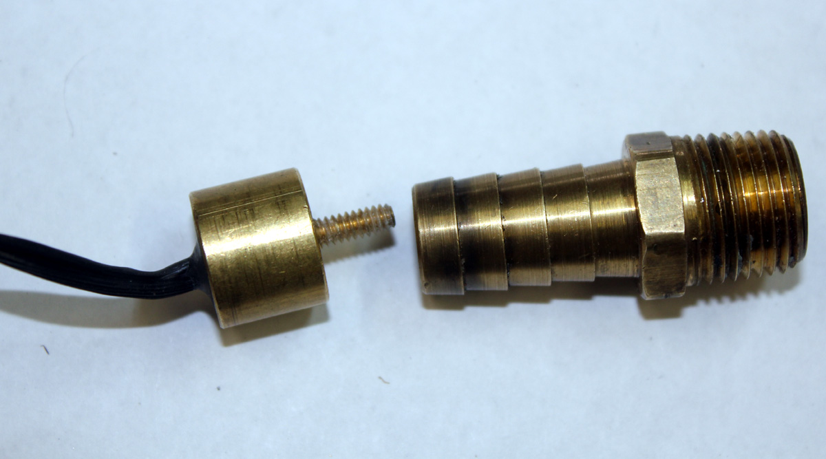
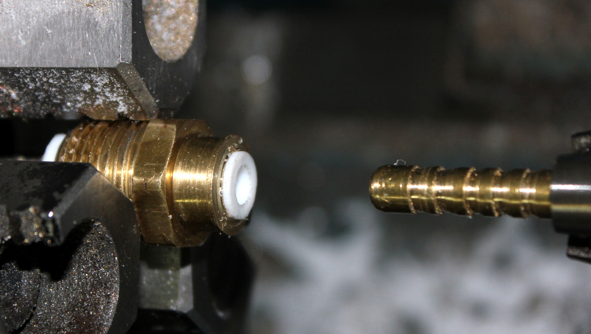
Ford (or any other) sensor. Derale provides the following sensor (left side
below compared to hose barb fitting):
I made a sensor adaptor out of a hose barb fitting. This
took minimal time and worked perfectly.
Derale intends for their sensor to be screwed onto a brass probe that pokes
though the radiator fins at or near the radiator outlet. That is a good location
for running the radiator fan, but I wanted to have a controller on my water
pump. The water pump has to run slow during warm-up, and come up to full speed
when the engine water is hot. I needed to control the water pump from water
temperature at the exit point by the thermostat housing.
Many sensors are improperly designed. The thermistor
should be thermally connected to whatever is being measured, NOT to the threads
or the housing. Connecting the temperature sensing element to the housing can
cause a problem. The housing becomes part of the thermal
measurement circuit, rather than just the probe tip that physically contacts the
air or water stream we are trying to measure. A poor sensor design causes
the sensor to partly read manifold temperature and partly read water
temperature.
My goal was to have proper sensor operation while finding a way to use
the original Derale thermistor assembly. I decided to make an adaptor (adapter) from a standard
brass hose
barb that fit my manifold port, a short piece of brass or copper rod, and a chunk of Teflon rod
to seal and thermally isolate the probe from housing.
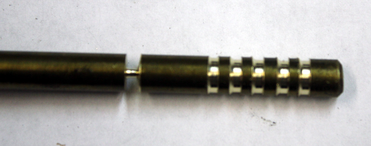
I machined the following parts. I make a barbed rod for
my probe tip. I put a taper on the ribs that allow it to push into a hole and
lock, just like a normal barb is machined. This is the tip that sticks down into
the water to probe the flowing water:
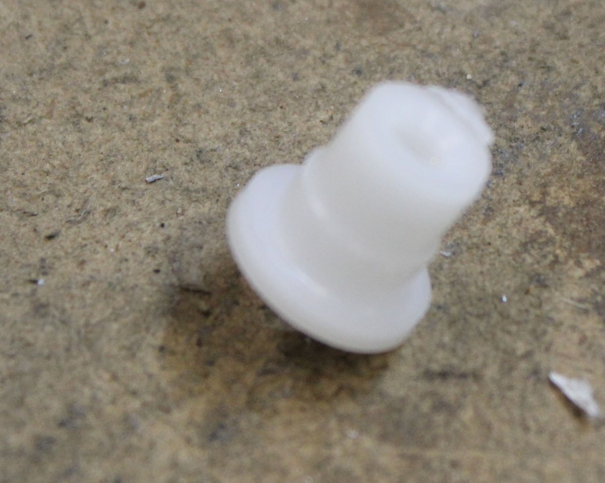
I machined a Teflon rod into an insert that had interference fit to the inner
probe and the outer threaded body:
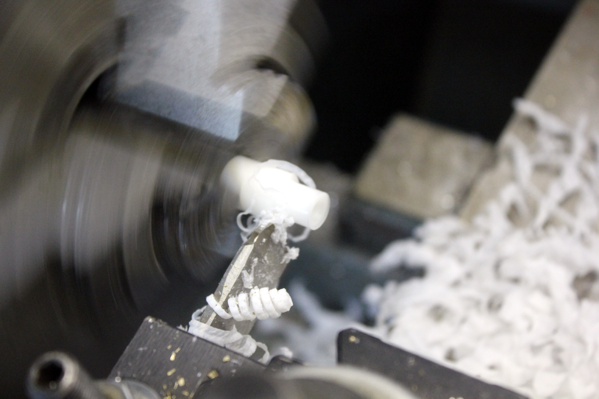
The result has a large lip for the water side and a step to match the inside
of the threaded fitting. This makes the water push it in tighter, no matter what
the pressure. This Teflon insert presses with an interference fit down into the
cut off and drilled hose barb fitting:
The probe ribs were machined into a barb angle. The severe interference fit, in
combination with the lip and barb steps, make a very tight pressure seal. The .250 inch
OD brass center probe insert has .075″ deep barb ribs that allow the insert to
be pressed in, but seal and lock it in place against pressure. Additional sealer
was not
necessary. It was leak and blow out tight even at a 100 psi test:
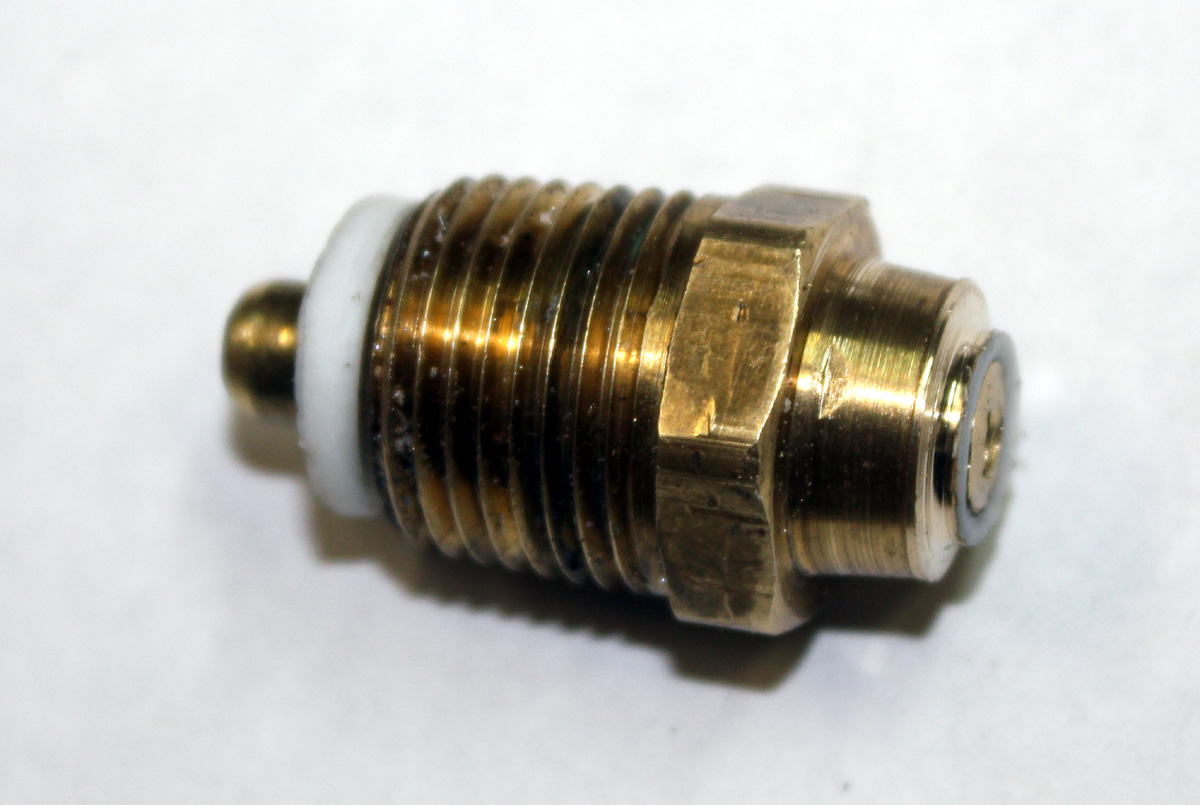
The final result look like this. The Derale sensor
screws into the blind 6-32 tapped hole on the right. The tip sticks down into
the water. The Teflon, which has very low thermal conductivity, prevents
manifold temperature from skewing water temperature readings:
The 6-32 hole in the insert allows the Derale thermistor
assembly to be attached like this:
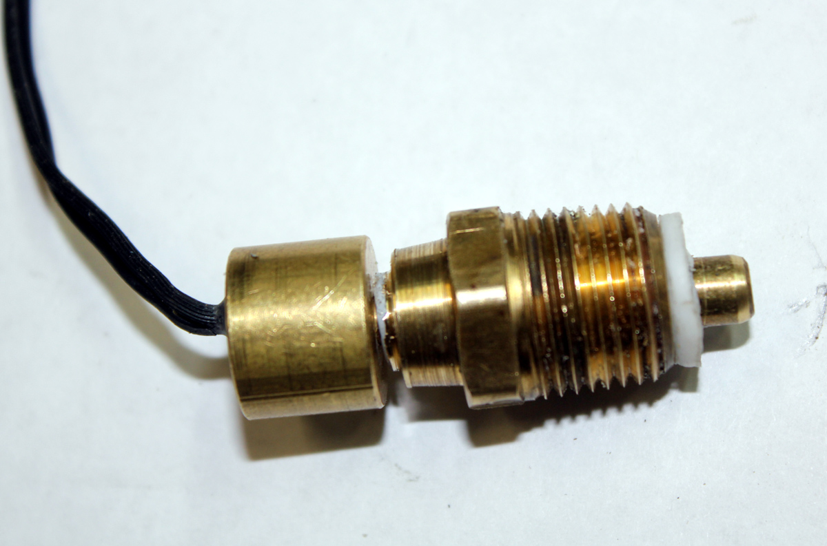
As an added feature, I run an electrical connection from the sensor housing
back to my car electronics. I did this by adding a lug between the Derale sensor
and the threaded rod that sticks into the water. This lug lets me sense the
small current that flows when the tip has contact with the coolant. When my
coolant gets low, I get a warning light.