End-fed Vertical and J-pole
End fed longwire or
random wire antenna
Understanding Gain differencesIn order to
The dipole is
A dipole does NOT
The plots below
You can see the
|
J-pole Antenna
Because the J-pole and Zepp are electrically identical in function, and are
similar to all other end-fed antennas in problems, pages on J-poles, Zepps, and
end-fed verticals overlap.
The J-pole and
other end-fed Hertz
antennas are prime
examples of antenna
that can have severe feed line common mode current problems. The coax shield has
to be at zero volts potential and have exactly equal and opposite currents
to those flowing into and out of the center conductor at the load and source, otherwise the
feed line radiates.
When we allow the feed line shield to be part of the radiating system, due to
poor feed system design or construction, the system can be unstable. With
improper feed line and mast decoupling, feed line and mast length and grounding
can affect SWR. Weather changes
can affect feed line moisture between the
outer jacket and the support for the feed line, and this can change SWR with rain
or snow. Even if SWR does not change, pattern can change significantly. For
example, just reversing the shield and center on a J-pole feed point can change
low angle field strength several dB, without affecting SWR!
Potentially severe common-mode
feed line problems of
end-fed 1/2 wave
antennas vary with feed line length and feed line routing. This is why some
people swear by
end-fed antennas, while other
people swear at end-fed antennas.
The J-pole is a good example of a poorly implemented feed system, because it
mixes balanced and unbalanced systems. In the J-pole, an unbalanced end-fed half
wave radiator is fed by a balanced 1/4 wave stub. The balanced stub is fed by
unbalanced coaxial cable. This creates two improperly treated
balanced-to-unbalanced junctions. Additionally, a metal support is often
connected to the J-pole antenna, adding a third variable.
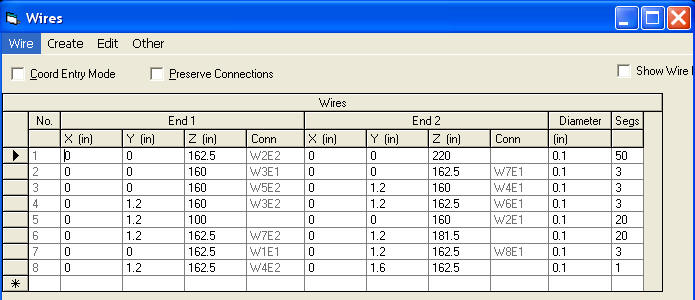
Here is a zoom of
the feed point in a
correct model of a
bottom-fed J-pole. Notice the model includes the coaxial feed line and/or mast
attached to the “grounded point” of the J-pole.
Wire 2 is the long vertical element
Wire 4 is the short vertical element
Wire 3 (obscured) is the horizontal bend (red circle the source)
Wire 5 is the mast and coax shield
You’ll see the
feed line or mast
grounds directly to
what everyone
assumes is a
“zero
voltage” point.
This is the
electrical
equivalent of any
J-pole with the coax
connected in series
at the feed point,
and the longer J-pole leg
connected to the
shield. The shield
can be connected to
any supporting mast
with much change in system performance. The feed line in this case is relatively cold.
Wire 5 can be moved to either side of the base. The side where wire five
attaches represents the side the mast and shield connects to.
Here is the
resulting pattern of the shield (wire 5) to short leg wire 4. This is with a split base feed, NOT
with the coax tapped
up on the “J” :
The gain is
2.37 dBi at 4 degrees
elevation (compared
this to 2.69 dBi for a 1/4wl
ground plane).
This is
actually the best
feed system for the J-pole! The
shield is connected to
the bottom of the short element of the J-pole, with the center
conductor connected
to the bottom of the longer
element of the J-pole.
This antenna model is in freespace, so earth reflection gain is not a factor.
It is essentially equal to a vertical dipole in the same environment.
There is some distortion of pattern cause by the imperfect feed, even though
it is the best feed.
Here
is the pattern with
the feed point
connections reversed.
The shield
is connected to the
longer element (wire 2 in my model) and
the center conductor
to the short
element (wire 4):
Low-angle gain
dropped about 5dB
with just a simple
reversal of feed line
connections! If the
model did not include
the feed line, the model
would never show
this problem. In
both
cases, the SWR stayed
near 1:1, yet low angle
gain
was reduced 5dB by reversing the shield and center conductor positions on the
antenna!
J-pole With Coax Tapped up on Stub
This is the model without coaxial feed line. The feed line shield would attach
to the open end of wire 8.
1 is the 3/4 wave element (1/4 wave plus 1/2 wave element)
6 is the stub
7 is the feed tap
With feed line of poor length choice:
Peak gain is now below the horizon.
None of this means the J-pole won’t work, have a low SWR, and make contacts.
It simply shows the pattern is unpredictable because the feed line, mast, and
grounding significantly affects performance.
In contrast, a properly decoupled 1/4-wave ground plane pattern:
This antenna is significantly shorter in height, has more gain along the
horizon, a smoother pattern, and is less sensitive to mast and feed line changes.
This is why commercial two-way radio manufacturers avoid J-poles. For
hobbyists, in particular with portable antennas, the J-pole is considerably
easier to build and it works OK.
Things Affecting J-pole Pattern and Gain
Affecting J-pole gain and pattern, but not included in models, are:
1.) Tapping the coax up on the J-pole can result in even worse problems.
This elevates the shield even higher in voltage.2.) Diameter, length, and area of the structure or mast the J-pole is
mounted on3.) feed line routing and connections
4.) feed line and mast length, diameter, and grounding
5.) Diameter and spacing of J-pole elements
Correcting the J-Pole Common Mode Problem
The J-pole cannot be fixed with a choke balun, or any common type of balun.
Let’s look at a few reliable cures for common mode.
Radials
Adding 4-8 radials helps a great deal, if we do it correctly. Here is a model
including coax and mast with 7 radials (wires 6 through 12).
J-pole feed point close up.
This elevation pattern is with the long element grounded.
This pattern is with the short element grounded, and the long element to
the coax center.
Cone or Sleeve Decoupling
In this case a cone or sleeve if formed to decouple antenna common mode.
The radials are bent upwards to form a vertical sleeve or cone. This
could be done with a hollow pipe, making the feed coaxial.
Elevation pattern
Drooping radial cone to isolate common mode
Pattern is clean but gain is reduced with drooped radial cone.
I-Max 2000 Solarcon
A-99 Antenna
The following
model is an I-Max
2000 5/8th wave vertical with a
vertical feed line or
mast connected to
the antenna base,
and no radials.
In this case I
picked one of many worse-case feed line or mast lengths:
feed line shield current
is 100% of antenna
current. This
illustrates why some users complain
about SWR problems
and RF in the shack
with end-fed
verticals like the
I-MAX 2000, while other
people do not
complain and seem to
love the antenna.
This is because some
people pick a lucky
mast height or
feed line length,
while others are not
so lucky. Unlucky people happened to choose
a mast height,
feed line length, or
grounding system
length that enhanced
common mode problems.
Here is the
pattern of an
antenna that copies
the I-MAX dimensions
and feed system:
Most of the radiation is up in the sky at a high angle. The angle is so high,
it is even useless for skywave.
This is a NEGATIVE gain antenna at low angles. A 1/4wl ground plane would
seriously outperform
the I-MAX 2000 or
any other 1/2 or 5/8th wl
antenna that does
not have a large
ground plane.
This pattern is over real earth, where a conventional dipole has about 8 to
8.5 dBi gain. This antenna about -2 dBd gain maximum. It has negative gain over
a dipole. The gain over a dipole at most useful angles
for DX is about -10 dB….significant negative gain.
Optimum feed line length and antenna mast height:
Even if we use
the optimum feed line
and mast length,
here is the very
best the end-fed
vertical antenna will do is this pattern.
In this case we
now have 2.67 dBi at 8 degrees elevation. This is actually an amount that is
unnoticeably less than a perfect 1/4wl ground plane
will produce! These severe
common-mode mast and
feed line currents
make
“no-radial”
verticals extremely
sensitive to
mounting height,
mounting structure,
feed line length, and
grounding. CB’ers for example often talk about grounding coax or changing coax
length to match an antenna. If changes in mast length or feed line length or grounding affect the
antenna pattern or SWR, it is an antenna design
problem.
The gain over a dipole is now a few db at some really low angles, so it can
be better than a dipole. At slightly higher angles for shorter skip, the dipole
takes over and can be several dB better than the vertical.
This change is entirely the result of altering height and feed line/mast length!!!
No antenna changes were made!
Summary End-feds
Without Grounds
ALL END-FED
ANTENNAS REQUIRE A
POPERLY DESIGNED
ISOLATION METHOD OR
METHODS, OR A VERY LARGE ground plane AT THE FEED, TO PREVENT
feed line OR MAST
COMMON MODE
CURRENTS!
Even ignoring pattern problems,
5/8th waves, Zepp
antennas, R7’s,
R5’s, or even common
J-poles do not have the stable SWR performance most of us might expect. While
poor patterns caused by lack of a flat dense far field ground will remain, lack
of a counterpoise or radial system at the base encourages harmful common mode
feed line and mast currents. The lack of proper counterpoise systems make
antennas dependent on mast length, mast grounding, feed line routing, and feed
line grounding. End-feeding
antennas is generally bad news
unless we include a stable low impedance counterpoise or
ground at the feed point.
A ground or ground plane without a supplemental feed line decoupling system
improves a system, but is no guarantee the system will be immune to feed line or
mast common mode currents. For example, a common directly fed
1/4wl ground plane with three or four radials will have common mode mast or feed
line currents. When I designed a commercial 1/4 wave ground plane with four 1/4 wave
long radials, I had to insulate the radials from the mast. I then needed to isolate the coax
shield from the mast and radials with a 1/4 wave stub that formed a choke balun.
Without the decoupling, I could change SWR simply by changing mast or feed line
grounding. The antenna feed impedance (and pattern) was unstable without
additional common mode decoupling.
While virtually no one looks at antenna patterns or gain, end users often
notice SWR issues. A few manufacturers learned from SWR performance problems in
the field. Cushcraft manufactured a series of end fed verticals called the “Ringo”
and “Ringo Ranger”. The Ringo series initially had a matching ring at the
vertical element’s base, but it lacked a ground plane or counterpoise. This made
the antenna very sensitive to what it was mounted on, and sensitive to feed line
lengths. People noticed that, at times being unable to obtain a low SWR with any
amount of adjustment or tuning. Cushcraft eventually had no choice, they had to
fix the problem. Cush Craft eventually added a separate additional ground plane
a predetermined distance below the feed point to control
the significant common-mode
currents generated by the lack of a suitable counterpoise at the feed point. Even that
solution is marginal, leaving some mast currents. At least the extremely bad
cases, where feed line or masts were just perfectly wrong and the antenna could
not ever be matched, were eliminated.
The Isopole
antenna used
multiple sleeve
sections to decouple
the feed line, and it
probably was one of
the best antennas
available for
immunity to feed line
coupling problems. It employed sleeve decoupling.
Common mode current problems become
worse when the
element is not 1/2 wave long. If we make a 1/2 wave antenna 5/8th
wave long, common mode significantly increases. Think of
this when we read
claims of
“no-radial”
CB antennas with
“3dB gain”
and a “low wave
angle”. No-radial antennas
have negative gain
at ground wave, or low (DX) angles, when compared to a properly constructed conventional
1/4-wave ground plane! Even when corrected and perfect, 5/8th wave antennas
barely have gain over a ground plane antenna. Instead
of focusing the signal at useful DX or ground wave angles, long end-fed antennas
without radials concentrate the signal toward a
neighbor’s TV set or toward an airplane flying
overhead. These unwanted common mode currents cause
the antenna
system to be
critical for
feed line grounding,
routing and length
and even allow
moisture on the
feed line jacket to
change performance
of the system!
To read more about end-fed antennas of various types, follow the end-of-page
link: