Fault Protection
Fault Protection
Related page,
metering systems
3-500Z under
typical fault
conditions
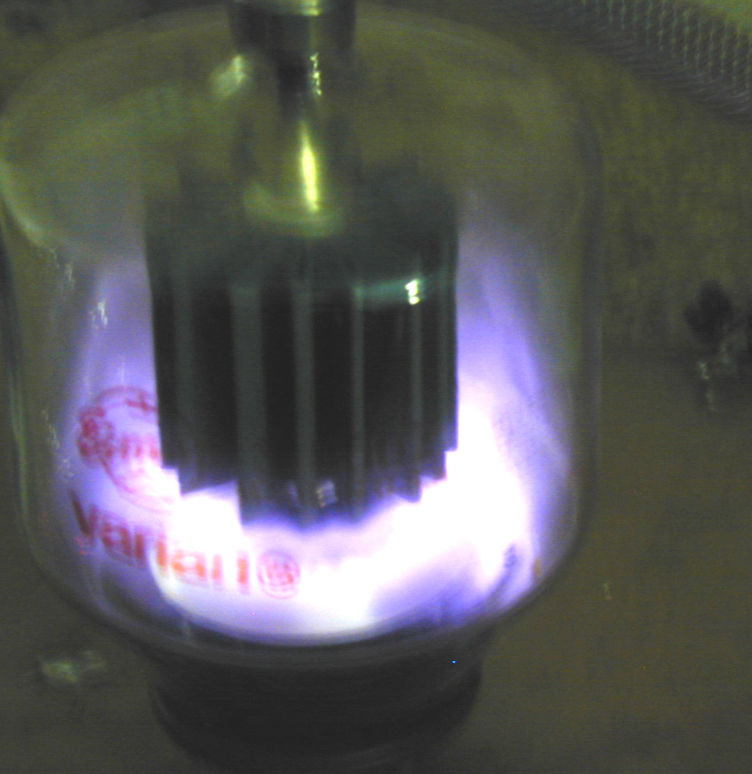
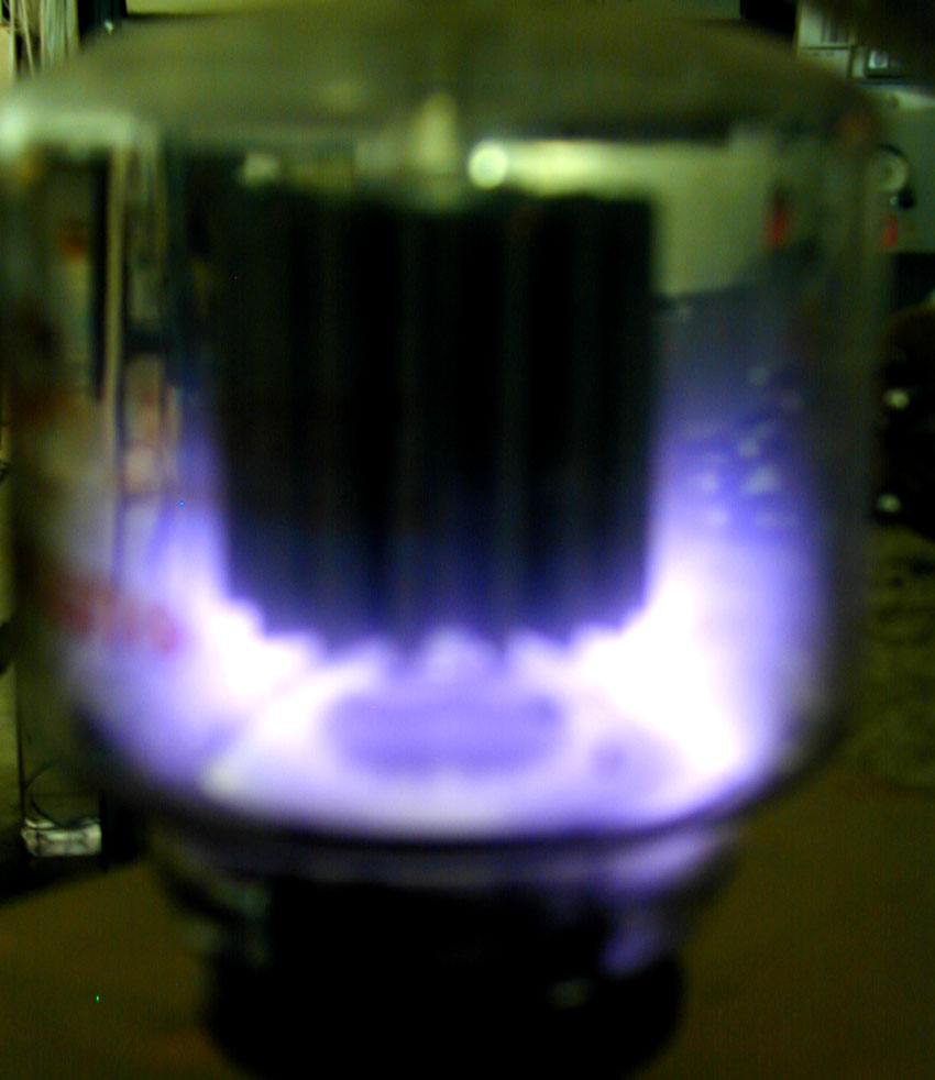
These pictures show a 3-500Z at the instant of flashover. The gas in the tube
has reached breakdown and ionized. The 3-500Z is behaving like a gas
discharge tube with very low resistance between anode and other elements!
In dozens
of amplifiers I’ve
seen with 3-500Z’s,
the fault is
primarily from anode
to grid support
cone. Since the area
is widely
distributed there
often are no marks.
You can see the
fault is
concentrated at the
edges of the anode
with a primary
target at the edges
of the grid support
cone. The area under
the plate is
actually plasma
free, as evidenced
by the dark color.
This particular
tube is into plasma
at 7MHz at 4500
volts peak RF
voltage. The primary fault path is from anode to the grid. This is not very often, if
ever, caused by
a parasitic. A
good tube isn’t any
more likely to arc
or fault from a “VHF
event” as it is from
normal low frequency
signals.
This
simplified circuit
shows the fault paths in an HF PA:
The typical
fault path is from
anode supply through
the RF plate choke,
from the tube anode
to grid, to
the chassis, and
back through the
grid and plate
current metering to
the negative rail.
D2 is a negative rail clamp. D2 protects the
meters. It limits
the negative rail to
chassis voltage to
about 1 volt under
surge conditions.
Note that only
one diode is
required, and the
best place for that
diode is from the
negative rail to the
chassis. It actually
is more effective to
place the diode
there than it is at
the meters.
The grid, being
directly between the
anode and cathode,
shields the
filament-cathode
from the anode. Very
little cathode fault
current flows unless
the grid is floated
on resistors,
chokes, or fuses. F1
in the grid is actually a very
bad idea.
Arc current is
limited by the
resistance and
impedance of L2, the
fault protection
resistor, the filter
capacitor series resistance, and the impedance of
the power supply
negative-rail-to-chassis
resistance.
Typical path
resistance would be
about 10-12 ohms
without the fault
resistor, and 20-22
ohms with it. There
is also additional
resistance inside
the tube.
If the high
voltage was 3000
volts, typical fault
current would be
under 150 amperes
with a fault
protection resistor
included, and 100
amperes with the
additional 10 ohms.
| About F1. Some articles suggest adding F1, either in the form of a grid resistor or fuse. F1 is a terrible idea! The grid should be connected to ground at all times.
About glitch resistors in general. Glitch resistors shoould always be in |
If grid fuse F1 opens
before supply
voltage dumps, we
have:
The GK diode
(inside tube) turns fully on. If
cathode saturation
current is exceeded
the grid-cathode
voltage will rise to
a value that causes
the grid to arc to
the cathode. Either
way, all the HV
dumps through the
grid to the cathode
instead of F1.
The danger of
this is the exciter,
if connected,
receives a transient
that may be hundreds
of volts. The very
sharp rise time of
the arc means we
essentially are
running a spark
transmitter
backwards into the
radio. D2 is no
longer in the arc
path of the circuit,
and so the plate
meter is exposed to
the full fault
current.
Instead of losing
F2 or D2, we now
greatly increase the
risk of damaging:
1.) The exciter
2.) D1, the
cathode bias system
3.) The tuned input
system capacitors
4.) The plate
current meter
The tube still
has just as much
surge current at the
arc strike, but now
has a sustained arc
at lower current
until some other
device having enough
hold-off voltage to
quench the arc
opens. This is why grids
should NEVER be
fused.
D2, negative rail clamp, is
removed:
If the tube had a
perfect
zero-resistance
fault, not likely to
happen unless the
grid touches the
anode, the grid meter
would try to move reads backward with
less than 167 amperes
flowing through the
grid shunt. The
plate meter would
try to read
forward with less
than 167
amperes flowing
through the plate meter
shunt.
This is why D2 is
necessary to prevent
meter or shunt
damage.
Adding rail clamp D2, we
have:
Adding D2, even
with a severe short,
nearly all of the
fault current flows
through D2.
In this case we
have 161 amperes
flowing through D2
and 5.7A through the
plate and grid meter
shunts. 167 amperes
flows from the grid
through F1.
Related page,
cathode fuse
resistors
Return to fuses and
grids
page