Tuning Aid TOF1
[ Home ]
Up Amplifiers
TOF Tune on the Fly Amplifier Tuning and
Protection Module
Amplifier Installation:
The TOF Module is available
at this link:
CTR
Engineering Inc TOF Link
Video Link to AL80B Demonstration
The TOF system will easily fit most amplifiers that use a
grounded negative grid meter system. The basic amplifier system looks like this:
If your amplifier has a grid meter at R3’s position, and it
has 12 volts DC available, it can be directly used. The TOF system, without
overload relay, draws about 3 mA at 9 volts. Because it has a shunt regulator,
the TOF draws 20-30 mA at 12 volts. This makes the TOF very easy to power.
While designed for standard grounded-negative supplies and
meters, the TOF can be used in virtually any metering system when its power
source is floated from ground.
The TOF, in most simple form, looks like this:
An indicator lamp flashes when a certain peak is reached.
About 20% or so beyond that warning level, and optional latching relay can be
use to disconnect things. A resistor sets the value of the overload, and of the
warning.
The TOF has internal provisions to represent the amplifier’s
grid meter internal resistance.
The internal relay system can be normally closed or normally
open.
Here is the TOF board:
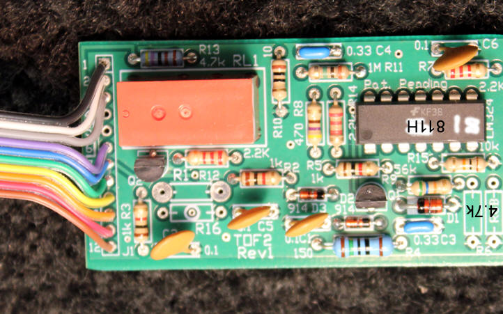
The ribbon cable pins are standard .1 inch spaced header pin
holes. The TOF can be ordered without ribbon.
For example, I have an amplifier bias control,
transmit-receive relay sequencing, and metering board that works with amplifiers
up to 10 amps plate current. That board accepts TOF modules for both plate
current and grid current. The TOF is piggy backed on that board.
The TOF can easily be adapted to read peak current, voltage,
or power in anything! It can be used to:
1.) read peak plate current, with a warning light and
disconnect relay
2.) convert a power meter to a peak envelope power reading
meter with a warning light and a latching relay
3.) read peak reflected power, with a warning light and
disconnect relay
Why Use a TOF system?
History of Amplifier Metering Systems
Prior to 1982, legal limit amateur HF amplifiers typically
monitored plate current on one dedicated plate current meter. Most
amplifiers had a second
meter that switched between grid current, relative output, and high voltage.
This system was used because FCC rules required simultaneous measurement of
anode supply voltage and anode current in any amplifier or transmitter exceeding
900 watts dc input power. All legal-limit amplifiers, by law, had to measure
plate voltage
and plate current at the same time. Since the FCC would not allow any legal
power limit amplifier that did not simultaneously display plate current and high
voltage, all legal limit one kilowatt amplifiers had at least two meters, one
reading HV and one reading plate current.
Around 1982, FCC rules changed. The FCC changed amateur power
levels from 1,000 watts dc input power to the final amplifier stage or stages,
to 1500 watts peak envelope RF power. This change completely eliminated power
amplifier output stage dc supply measurement requirements. Despite this FCC rule
change, most amplifiers continued the old tradition and legal requirement. New
amplifier were never rethought. They still continuously monitored plate current
on a dedicated meter,
switching a second meter between multiple functions that included HV or having
additional meters.
Keeping plate current on a dedicated meter was a mistake. Grid current, screen grid current with multi-grid tubes and
control grid current in grounded grid triode amplifiers, indicates proper drive and tuning
far better than any other easily measured parameter. As a matter of fact, an
experienced tuner can adjust an amplifier perfectly only watching the proper
grid parameter.
In 1982, I switched all my amplifier designs to continuously
monitor grid current, with plate current moved to the multimeter. I did this
because the grid meter, more than any other parameter, indicates proper tuning
and operation. This was an improvement from old-school metering, where one meter
read high voltage or grid current and the other meter read plate current.
Continuous grid current metering was much better than
prior systems, because grid current indicates proper amplifier tuning more than
any other single parameter. Even if a tuning pulser or “pecker” is used, you
have no idea if you are properly tuned, or overdriving the amplifier. Despite
what others might say, you still need to know the peak grid current! If grid current is not checked, there is
significant risk of amplifier overdrive, amplifier damage, and/or splatter.
Standard current meters only read accurately with steady
carriers. Unfortunately, metering systems to date have used a
pseudo-average grid current meter. Without resorting to a carrier, standard metering systems do not
even come close to indicating actual operating grid current. The common meter
system requires switching to a carrier mode, and applying the maximum expected
drive power to check for proper grid current and drive/tuning. The drawbacks of using a carrier
to read grid current are:
- A steady carrier is particularly hard on small tubes, like 811A
tubes - The steady carrier grid current is often not the real peak current
- A tuning pulser will not show grid current in normal
metering systems - During voice or Morse transmissions, the operator has no
idea what true grid current is
I thought about a better way to tune and monitor amplifiers.
The TOF system solves the overlooked but major problems inherent with tuning pulsers or peckers. Besides a greatly improved
running indication of proper drive
and tuning during operation, the TOF system allows tuning (and monitoring) on
the fly. The operator can adjust drive or loading while operating amplitude-varying modes,
such as SSB or AM. This improved tuning method makes it virtually
impossible to have two of the most damaging operating conditions, which are
accidentally over-driving or accidentally under-loading the linear amplifier.
This system will also detect the most damaging of antenna failure problems. This system
will work with most other amplifiers, and plans are to eventually cover all
amplifiers including solid state applications.
| Patent Pending
I generally do not like patents, but some have a tendency to use other’s ideas or creativity to profit. They either make The pending patent application is for the application, concept, and operation, |
System Overview
Grid meters are the single most important indicator of proper
linear amplifier operation. This includes screen grids in grid driven tetrode
amplifiers, and control grids in grounded grid triode amplifiers. Almost every vacuum tube amplifier
will benefit from this
system, and it could even be included in certain solid state amplifiers.
This system modifies the grid current metering system in a
unique way. This modification provides a constantly available indication of
peak grid current. By watching peak grid current, the operator has a
continuously running indication of improper tuning or excessive drive.
This system includes a bright warning LED, and provisions for an overload
relay. The LED flashes when grid current peaks exceed to the optimum operating
value.
Lack of accurate reading during operation, when absent a
steady carrier, causes at least three problems during operation. This also
applies if you use a tuning pulser, ditter, or tuning pecker to tune:
1.) peak grid current will no longer be the same because peak
exciter power changes
2.) peak grid current will no longer be the same because
average amplifier voltages change with different power supply demands
3.) if the antenna system changes or drive power changes for any reason, affecting
amplifier operating parameters in a harmful way, you have no indication or alert
on the amplifier meters
In addition to the above, when a tuning pulser
system is used and you tune exclusively for peak output power, you really have
no idea what the grid current actually is. This system eliminates the largest
problem that always occurs when tuning with a tuning pulser which is not knowing
the true operating grid current.
This system allows the CW, SSB, or AM operator to immediately
notice improper operation or tuning. With the addition of an external
power meter, or with proper skill and the TOF alone, the operator can tune and
monitor for optimum operation
during normal voice, on any mode including AM, without external aids.
It also allows tuning without loading to maximum peak power at full drive. The
TOF1 also eliminates very common tuning errors caused by line voltage sag or
power supply sag under carrier conditions. Once properly accustomed to tuning by
grid current, nearly any operator should be able to adjust for
optimum output and minimum distortion.
To make installation easy, the TOF leads are color matched to
AL811 wiring. Please review the instructions below and be sure
you are completely comfortable with installation.
The base TOF1 for the AL-811 amplifier series has five basic
connections. The TOF1 should take about 30 minutes to install, the TOF1A
and H slightly longer.
LED Warning Light
All TOF models include an LED warning indicator.
R6
sets the LED warning point. R6 is:
| AL811 | 3.3k |
| AL811H | 4.7k |
| AL80B | 5.6k |
The LED will occasionally blink red with normal operation. If
you are overdriving the amplifier, or have the amplifier under loaded, the LED
will stay on longer. If you find the LED hanging on for more than brief flashes,
drive power is too high or the loading control is set too far closed.
Over-current Relay
The TOF1 can include an optional over-current relay. This
relay has normally open and normally closed contacts. The contacts can serve
many functions, including amplifier
trip-off for mistuning.
Later models will include a provision for ALC control. This
will result in improved ALC operation in almost all amplifiers.
Cost and Availability
The base TOF has no overload relay, but does have provisions
for an LED warning lamp. The base TOF1 currently sells for $55.00 US, plus $8
shipping and handling for priority mail. I will have to advise any additional cost to other countries,
but most countries would fall under the $8.00 shipping price. Please specify the
amplifier you have.
I accept PayPal to my normal email address. Type this in:

The TOF1 with overload relay is $68.00 plus $8.00 S&H.
Stock may be limited depending on sales. This is a new
product, and price may change as my cost varies.
Typical Operation Overview
Amplifier operation with the TOF1 is normal, with the
exception the grid
current meter indicates peak current. Operators can observe maximum grid current
on any mode, including AM or SSB. Excessive peak grid current indicates amplifier mistuning or
excessive drive far better than any other system, including output envelope
oscilloscopes. The results below
show an ICOM 751A driving an AL811 three tube amplifier. Tuning was accomplished using
only the TOF1 with normal SSB speech to the amplifier. Although the
amplifier was tuned on SSB voice, the TOF works to tune with any
mode. The TOF system works with any tuning pulser, and results are far more
accurate than using the tuning pulser with a power output meter. As a matter of
fact, a tuning pulser should probably never be used without a TOF system,
because without a TOF you have no idea what the operating grid current is.
Results
The AL811 tested was representative of any used AL811
amplifier. The was operated on 120 volts from a rather loosely regulated bench
outlet. This outlet including 50 feet of number 14 AWG wire, and would be
typical of most modern home wiring systems. The radio was an IC751A ICOM,
and power was measured with a calibrated Bird peak reading digital meter.
I tuned the amplifier with full drive from the IC751A on
twenty meters, using normal voice. The amplifier was adjusted for 140 mA
absolute maximum grid
current during normal SSB speech.
Tuning this way without the TOF, and without
using SSB voice, will damage amplifiers or result in excessive splatter!
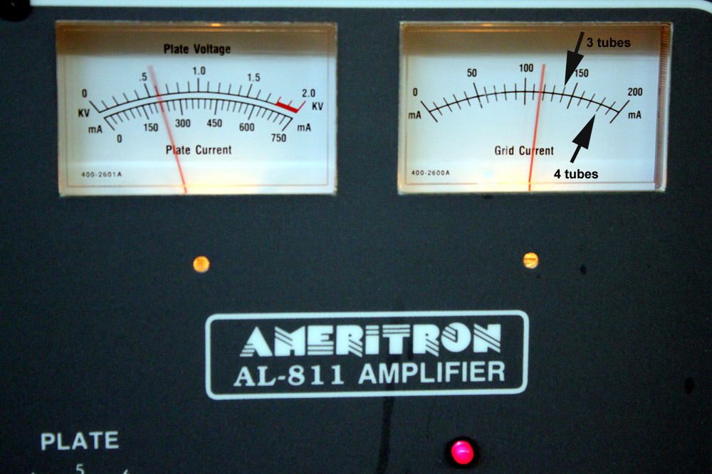
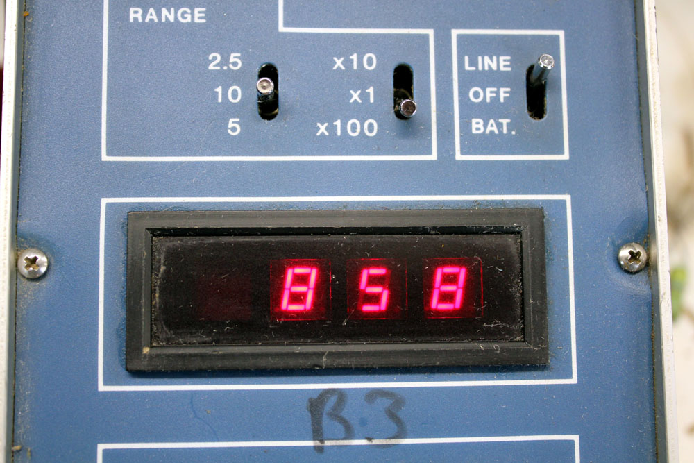
Tuning was adjusted so grid current just flicked up to the
three tube mark. In this case the average anode current is 225 mA, and the peak
grid current is around 120 mA with occasional flicks to 140 mA. Anode heat is
well under safe tube ratings. If this was a carrier condition adjustment, the
plate current would be nearly pinning and the tubes would be well over safe heat
limits. Grid current would be the same.
The display below is a two minute storage of peak spectrum
levels. This would be worse case splatter, because all peaks are stored at their
peak level. Actual over the air signal would sound better, because occasional
spits and spatters would not push the S meter or AGC up so high.
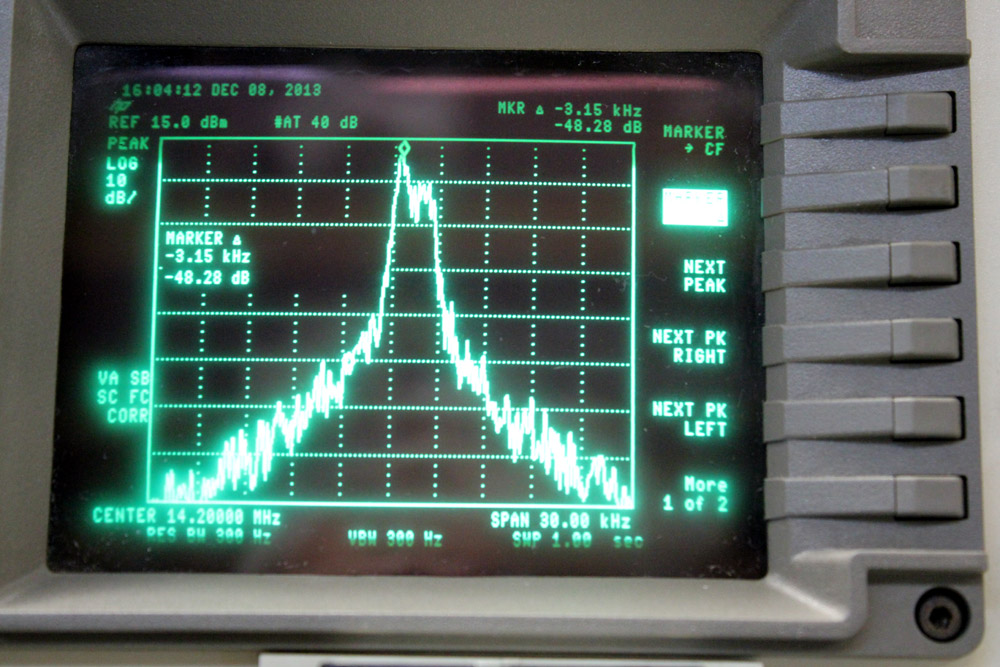
Lower side spurious was -48.28 dB peak at -3.15 kHz.
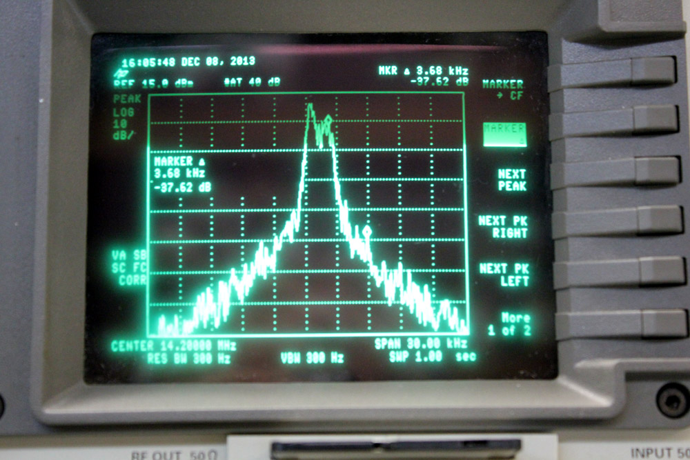
Upper side spurious was -37.62 dB peak at +3.68 kHz.
These results were about 10 dB better than tuning the
conventional way with full drive, and 6 or 7 dB better than using a tuning
pulser. The disparity between
tuning with the TOF and tuning with carrier or pulser is from power supply sag.
When the amplifier is loaded with
continuous plate current, rather than normal voice plate current fluctuations,
you will not get a good indication of peak operating grid currents.
I do not recommend full drive of 100-watts into three tubes,
even though this signal was not significantly worse than the ICOM barefoot. The
purpose of this is to show the improvement afforded by tuning during voice, and
watching peak grid current. Typical maximum grid currents for several popular
tubes is show in a table below.
All values are per tube with full airflow
| Tube Type | Dissipation | Peak Grid Current | Typical drive power SSB PEP or CW carrier | PEP SSB voice output power or CW carrier |
| 811A | 65W | 50 mA | 20 watts | 200 watts (brief or low average) |
| 572B | 160W | 70 mA | 40 watts | 350 watts |
| 3-500Z | 500W | 140 mA | 60 watts | 750 watts |
| 3CX800A7 | 800W | 20 mA | 40 watts | 800 watts |
| 8877/3CX1500A7 | 1500W | 40 mA | 90 watts | 1500 watts |
Note: Table is approximate values.
Actual amplifier, including high voltage and other variables, determine exact
values.