|
811A Tube History and Construction
Modification to AL811 (and other 572/811 amplifiers with
standby stability issues)
Occasionally AL811amplifiers (three tube versions) have been reported to
cause receiver noises, like a popping or broadband noise. This noise might also
be faintly heard from the rear panel area of the amplifier as a muted buzzing or
clicking noise. The noise changes, starting and stopping and changing rates, as
BAND, PLATE, and LOAD settings are changed. This happens only on standby. If the
amplifier includes gas protection tubes on the filaments, the gas tubes will
fire on upper bands under certain settings of TUNE and LOAD.
This problem appears to be related to the cutoff characteristics of the 811A
tubes. There are more details at this page
811A tubes . Tubes with
sharper cutoff have this particular problem, while tubes with more remote cutoff do not.
A 4.7K filament load resistor, shown as R100 in the schematic below, totally stabilized these tubes. Unfortunately, there is no assurance
that value
will stabilize all tubes in all amplifiers, so it would be better to use the
lowest possible loading resistance on the tube filament system. Note
that the FL2100 has stability issues with some tube types while on standby.
These mods are a potential source for improving FL2100 stability, because they
terminate the FL2100 cathode system in a wideband resistive load, even while the
FL2100 is on standby.
The Ameritron AL811 will eventually switch
to a pair
of 200 ohm resistors in parallel (~30 watts each) as a production modification.
This change results in increased drive power requirements, making the AL811 more
comparable with 100 watt exciters. At the same time, the heavier load on the
filament-cathode system will compensate for variation in commonly available
import tubes. The extra load resistance unfortunately requires tuned input circuit
changes, so it will not be an easy field modification.
We can reasonably assume 572B tubes, since they use the same grid assembly and
filament, also have this tube manufacturing consistency problem.
It is better to add something, even if less-than-ideal, to load the RF path at
the filament in all 811 amps and 572B amps.
Worse case RF cathode voltage for 811 and 572 tubes is around 100 volts. Typically, at full drive,
peak cathode RF voltage is around 75 volts. The resistor dissipation rating should be

| 2.7K |
2 watts |
| 1.0K |
6 watts |
| 470 |
12 watts |
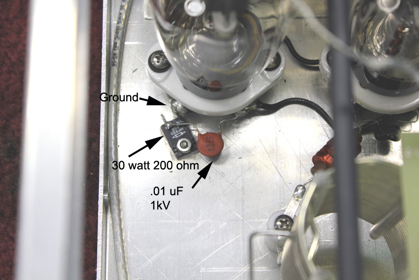
| 200 |
28 watts |
The added resistor should be a low inductance metal oxide type. Any
load resistance above 200 ohms will have minimal effect on input SWR. This could be
as many as 13 2.7K 2-watt resistors in parallel, or any
combination of resistors in the chart above. Do not use
wire wound resistors, even non-inductive wire wound resistors.
The popping occurs when a sharp cutoff tube has the input and output open
circuited. Adding resistor R100 will load the cathode system of the amplifier.
Rsb is the typically seen, but generally unnecessary,
self-bias resistor. Adding this resistor makes the problem much worse.
The Al811, without any resistor at Rsb, floats to full cutoff. This is
normally around 40 volts positive. The problem centers around tubes that only
develop around 18-20 volts, or less, self-bias.
A resistor of 200 ohms or more will have negligible effect on input SWR.
It will help prevent popping or noise while on standby.
Modification to Eliminate T-R Relay Chatter
On some bands under some tuning conditions, the TR relays in AL811 series
amplifiers using split relays can chatter.
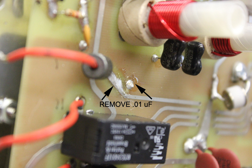
This problem is caused by poor location of a .01µF
disc capacitor.
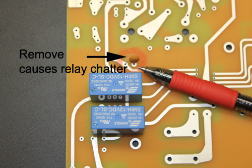
Break or cut this capacitor off the board.
|