|
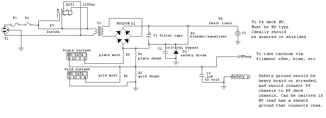
Let’s work our way left to right through this power supply and
see why certain components are used and what characteristics are important in
those components.
Step Start or Inrush Limit
R7 and RLY1 make the simplest possible inrush limiter. In this system RLY1
generally has a pull-in threshold of around 70% of rated voltage. This means all
primary current flows through R7 until the capacitor bank reaches about 70% of
full voltage. This greatly reduces inrush. R7 should ideally be sized to limit
current to maximum safe operating current, or some amount less at your
preference. If the line is 250 volts (there is no 220 in the USA, that went away
in the 1950’s) and the primary system safely tolerates 15 amps at worse case
load, we would want R7 to be at least 250/15 = 16.7 ohms. Use the next
highest standard value, or more if you prefer. If you too much resistance the
amp will not reliably close RLY1.
Let’s say we use 20 ohms with 240 volts. On switch closure when the primary
looks like a near-short, inrush would be 12 amperes. If the supply was loaded
with more than 1000 watts load before RLY1 closes, the relay may not close.
Because of this it is a good idea to use an energy storage or pulse rated
resistor that handles significant surges without failure, and to fuse the
resistor (fuse is NOT shown) with a modest
current fuse. Typically a 2-amp slow blow fuse will handle a 10-amp inrush
system for the short duration of R7 current. Size the fuse as small as possible
consistent with the fuse not opening on normal starts. The system below is a
120V system.

Whatever you do in a high-power variable-load capacitor input supply, never
put the inrush protection or limiter as a fixed resistor in the primary or
secondary!
A capacitor input supply operates with very high apparent power factor. Any
resistance pre-filter capacitor will dissipate far more heat than most people
expect, and will also cause a much larger voltage drop than expected.
A capacitor input supply conducts only over a small fraction of each cycle.
With a short conduction angle, peak currents are very high. NEVER just add a
series R on the AC or unfiltered DC side of a supply that has variable load, or
has a high power drain. Adding a resistor that is in-circuit all the time on the
AC or unfiltered DC side ruins transformer regulation while making excess heat.
If you are going to spend money on a resistor suitable for the B+ line, put it
on the DC output to limit sure (Ohm’s law can be directly applied without
consideration of power factor there), and put a real step start in the primary.
Link to power
factor heating of transformers and resistors.
Transformer Selection
Everyone is probably going to pick their own filter caps, bleeders, and
diodes, often by gut feeling rather than science, so I’ll not specify capacitors
or rectifier design. There are many Internet suggestions that sound logical but
are really are foolish, so be careful.
My only warning will be to NEVER use carbon resistors for equalizing
resistors. Carbon is a semiconductor, and semiconductors have less resistance if
subjected to thermal overloads. High dissipation carbon resistors can actually
fail shorted. That’s a bad thing on a power supply.
Note D2 and C2. Both are critical safety components. When properly sized D2
and C2 will protect the meters, meter shunts, and the operator under any
condition of HV fault. Use the lowest voltage C2 available in a small disc
capacitor. I typically use 50 volts. The value generally is a .1 uF. This
capacitor serves two functions, bypassing D2 for RF and providing an additional
clamp at 100 volts or so if D2 should ever open. D2 can be any diode that can
survive, without destroying the case and opening, a current of HV over R4 plus
worse-case path fault resistance. Fault path resistance would generally be the
sum of filter capacitor ESR and R4’s resistance.
R4 typically should be chosen to limit fault current to non-destructive
values, typically in small amplifiers (below 5 kilowatts output) this winds up
being a path resistance about 5 ohms per 1000 volts. A 4000 volt supply
would typically require around 20 ohms fault path resistance. Typically that
path resistance would be comprised of 2.5 ohms ESR in the capacitor bank and 2.5
ohms total in wiring, RF chokes, and other resistors. In this case R4 would be
15 ohms, which adds to the other wiring and component resistances for a total
fault path resistance of 20 ohms.
With 4000 volts we would have 4000/20 = 200 amperes fault current. A
1N4007 would only
handle 30 amperes before becoming unreliable and shorting, but that does not
mean it would burn open. We really have to test diodes to see how much pulse
current blows the case open. Better quality 1N4007’s will handle 100 amperes for
30-50 milliseconds, and 1N5408’s over 200 amperes for the same time period. If
you are unsure, use a 1N540X series diode, like a 1N5408.
D2 may require more than one diode in series. If the grid or plate shunt
drops more than 0.5 volts, you would want to add more diodes in series at D2.
Allow 0.5 volts per diode.
|
