|
Arcing in Tank Circuits of HF
PA
This test circuit is easy to duplicate, and demonstrates
the extreme voltages that appear in an amplifier when the load is improper for
the amount of drive power applied.
Years ago, almost every amplifier had a output transformer.
The transformer was similar to tanks circuits in RF PA’s, in that it transformed
or matched impedances. Even though Q was very low, the transformer could still
store and release energy.
Experienced people knew if the volume was turned up too high in a
transformer-coupled output stage, and if the load was absent, voltage across the
transformer would soar to many times the normal operating voltage. No load or
grossly mismatched loads often resulted in damaged transformers, blown output devices, or other output circuit
component failures.
Failures induced by load or matching faults would occur in conservative
amplifier designs, where components would last years in continuous proper operation.
An audiophile would NEVER think of operating his expensive tube-type amplifier
at anywhere near full volume into an open load, let alone a load where grossly improper impedances are selected in amplifier output-transformer taps.
Blame was never placed on stability. Everyone knew and
understood conservatively designed well-constructed amplifiers with energy
storage systems of any type, even very low Q systems, would still produce
over-voltage failures when grossly overdriven or improperly terminated.
TV manufacturers used this well-known effect to advantage
in horizontal output sections, where a flyback transformer with moderately low Q
would produce many times the actual turns ratio in peak voltage, because of
energy storage. Even modern switching supplies and our automobiles depend on
energy storage to produce entirely new voltages, far above supply voltage,
without requiring parasitics or high Q.
RF Systems
RF systems are certainly no more immune to mismatch than audio
amplifiers, they very often are much worse. RF circuits are generally single-ended, and
tube-type amplifiers have moderately high-Q (efficient) energy storage tank
systems. Single-ended amplifiers with conduction angles under 360-degrees almost
always contain intentionally designed fly-back systems, where tank
circuit Q re-creates the missing portion of a sine wave from the half-cycle (or
less) tug of the single-ended output device.
Somehow we have forgotten all this, and allowed ourselves
to be misled into believing it takes a circuit or design flaw producing an
oscillation to cause an arc or component failure.
This article demonstrates how easy it is to produce very
high voltages from normal perfectly stable PA’s with normal tank systems.
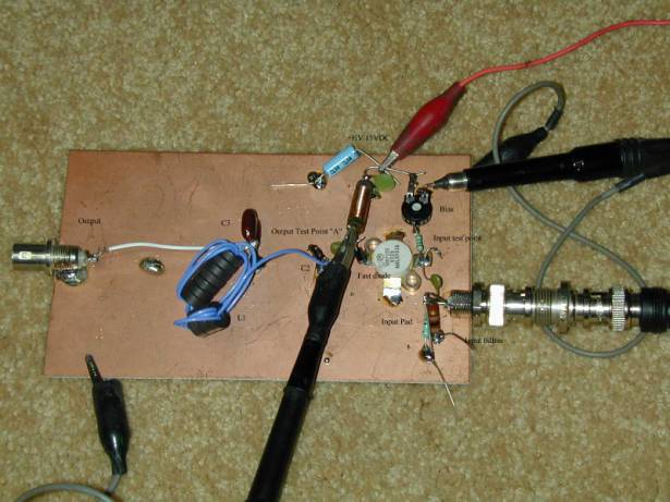
Demonstration Circuit
It isnt safe to poke around in a high-power vacuum tube
amplifier while looking at voltages, but a simple demonstration circuit can be
constructed.
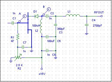
C1 is driven with a signal generator, L1 is selected to
match the FET output to a 50-ohm load. The FET is operated at low current and
has a series fast-switching diode, to simulate a one-way conducting vacuum tube.
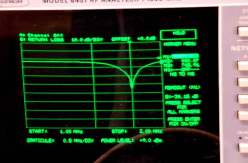
This system was matched at 1.8MHz using the return-loss
function of a network analyzer.
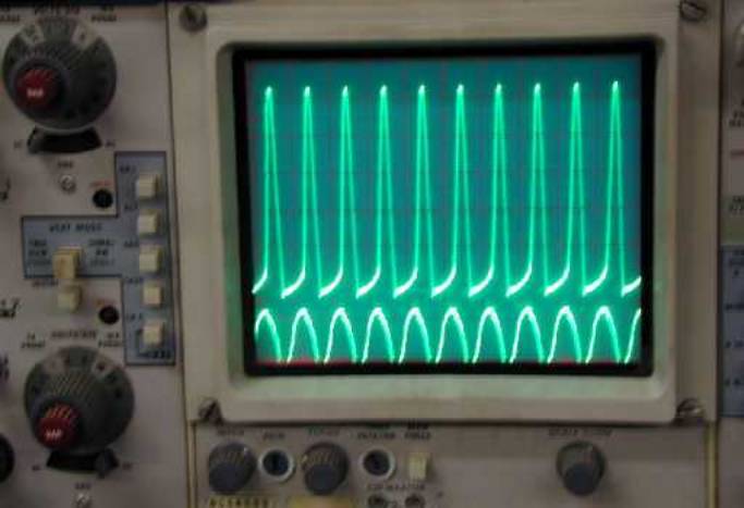
0dBm drive was applied with a signal generator, and the
resulting waveforms appeared:
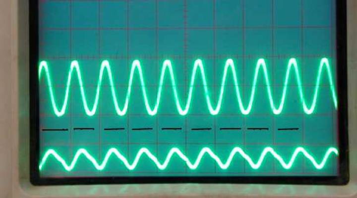
The upper trace is the output at D1 anode (point B).
The black-dashed line was set at zero-volts. The scale is 10v/div.
The lower trace is drive voltage (point A). The scale
is .1volt per division.
From this we see peak drain voltage swings approximately 20
volts, from around 5 volts to around 25 volts. This would be normal operation of
a PA stage.
If we increase drive power and overdrive the PA, we get the
following voltages:
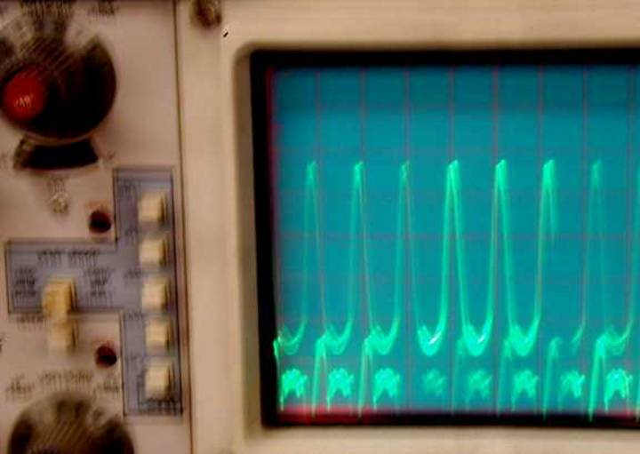
We now see the peak drain voltage is almost 50-volts from a
15Vdc supply! In a 3000V PA stage, this would be 10,000V peak! It should make
sense that amplifiers arc from grossly excessive drive power.
The next question would be what makes a normally driven
amplifier arc. Often is when the load is inadvertently disconnected, either
through poor relay timing, a bad cable or connection, or perhaps a failure in a
component between the antenna and the amplifier.
Here is a scope picture with normal drive, but the load
disconnected:
The
drive voltage has
increased slightly
because of feedback
through the FET, now that the drain is swinging wildly almost 70 volts, all from
a 15-volt supply. This would be the electrical equivalent of 14kV on the anode
of a 3-500Z operating from 3000Vdc!
Conclusion
Its easy to see why perfectly stable HF amplifiers, if overdriven or
operated at moderate drive levels under conditions of a load fault, can be
damaged by severe arcing.
Virtually all PA arcs (other than those caused by component
failures or reduced voltage breakdown from dust or contaminates) occur when the
load is interrupted or mismatched, and the PA no longer transfers energy to a
proper load.
The vast majority of PA failures are caused by improper
operation or defective components, not by “strange events” that are
unpredictable and non-measurable.

|