Also see
Amplitude Modulation
page
My
Valiant Audio Mods
Johnson Valiant
The Ranger and
Valiant Audio System
When I was first
getting into amateur
radio in Toledo,
around 1960, I
mostly listened to
160 meters. I was
awestruck at how
powerful and clear
Ranger and Valiant
transmitters
sounded.
Johnson Ranger
and Valiant
transmitters had the
best audio on 160
meters. Johnson
engineers did a good
of sizing
components. They
obviously intended
the audio system to
roll off lows and
accent highs to give
the signal more
“punch”. Johnson
designers did not
get carried away
with accenting highs
as badly as Heathkit
did in the Apache,
DX-100, and other
rigs.
We really don’t
need to tear-up our
classic equipment to
get have excellent
audio with our
Ranger and Valiant
transmitters.
Provided other
components are in
good shape, changing
value of a few
capacitors will do
everything
necessary. Unlike
many other AM rigs,
the classic Johnson
transmitters had
pretty darned good
audio systems.
Caution with Those
Hammers and Torches!
While I’m sure
the intentions are
good, there are many modifications
that do not actually
do what is claimed.
Some are not
seriously harmful,
mostly giving a
false sense of
“improvement” but
causing no real
harm. Other mods,
unfortunately, tear
up or cannibalize an
otherwise pretty
good piece of
classic AM equipment.
There are many
excellent sounding
signals with no more
than good
microphones and good
audio adjustment on
stock transmitters.
With a few simple
mods, the
good-sounding
transmitters can be
optimized for strong
signal ragchews.
Some audio system changes
remove nearly all
upper frequency
rolloff. If we want
those “ssesses” to
stand out in speech,
we might want to
extend high
frequency response a
bit beyond the ~4
kHz Johnson used,
but we should also
remember this does
nothing for
communications
through QRM or
noise, especially on
crowded bands.
Collins, and
everyone else in the
communications and
broadcasting
industry, already
realized
broadcasting
extremes of speech
frequencies only
helped when
signal-to-noise
ratio was very high.
The extra lows and
highs sounded great
when loud, but
seriously reduced
communications
effectiveness when
signals were weak. If
we
listen to the bassy
AM operators when
signals are weak, we
find they are very
difficult to copy
when compared to normal
communications
audio. Collins
worked this all out
many years ago,
settling on an
optimum passband for
readability. It
wasn’t 10Hz to
10,000Hz!
Over-emphasized bass
and treble removes
power available for
the 300-3300Hz range
so important for
communications, and
taxes the
transformers so much
that we run a
serious risk of
damaging expensive
transformers. At the
very least,
excessive lows and
highs increase
intermodulation and
bandwidth, ruining QSO’s up
or down the band
from splatter and
irritating other
operators,
who sometimes make
it a point to return
the
“favor”
and retaliate
against and
disrespect all AM’ers.
There is a second
issue sometimes
missed in the
Johnson audio chain. The
later stages of the modulator section
show increasing
phase shift at very
high audio
frequencies. When
the rolloff is
eliminated at
frequencies we can’t
use anyway, and if
we add audio
feedback, the
negative feedback
can shift phase and
become positive
feedback. This can
make the audio
system unstable.
Mods that radically
extend lows subject
the modulation
transformer to
high-energy low-frequency bass
frequencies (that do
nothing to improve readability).
Finally, I don’t
believe the people
who designed your
Ranger were so
stupid or careless
that they made a
mess of the total
audio system. It
would be normal
engineering practice
to design a good
system, and then
adjust one component
to tailor slope. My
bet is they
intentionally sized
C52 to increase
audio punch at the
expense of making
people sound like
Ted Baxter.
The Diode
“Super-modulation” Modification
One popular
change is the
addition of a
silicon rectifier
diode, or a group of
diodes in a fancy
circuit, in the modulation
transformer
secondary. The
thought or claim is the
diode or diode
network limits
negative peaks and
prevents splatter.
It does this by
preventing the anode
from going below zero
volts on negative
modulation peaks. This is
sideways-thinking
for two major
reasons:
1.) Going to
zero-carrier is
actually not what
causes splatter or
excessive bandwidth.
The slope of
waveform abruptly
changing,
going in a new
direction towards a
straight line, causes the signal to
get wide. It’s
really a “Fourier
problem”, where the
rapid change in
slope requires
high-order harmonics
to produce the
waveform.
2.) A plate
modulated tetrode
tube, contrary to
what we might assume
from causal
understanding of
plate modulated
stages, reaches zero
carrier long before
the modulated high
voltage reaches zero
volts. The diode
limiter will limit
too late, unless the
modulated stage uses a hard class-C
low-mu triode in the
PA.
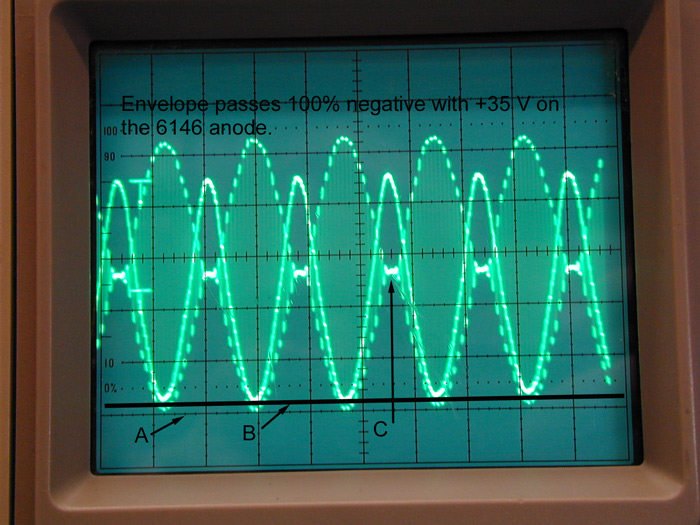
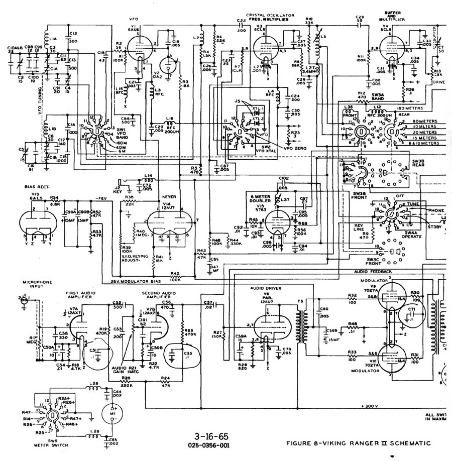
This is the
modulated high
voltage supplied to
a Johnson Ranger II,
along with the RF
envelope in the
second trace.
Line A was set for
zero anode voltage
Line B is
approximately 40
volts positive for
the modulated anode
supply voltage (200
volts per division
for this channel
with zero voltage
set at scope
graticule A)
Point C shows the RF
envelope cutting
completely off (over-modulation) even
through the
modulated high
voltage never
reaches zero volts.
Peak anode
voltage is around
920 volts, operating
anode carrier
average voltage is
510 volts. This
includes modulator
secondary voltage
drop.
Notice the high
voltage does not
have to double on
positive peaks, and
does not go to zero
on negative peaks
even though the
stage is slightly
over-modulated. This
is because the
modulated stage is a
tetrode, NOT a
triode! The
modulated stage has
both screen and
plate modulation
applied, as all
tetrodes require.
Triodes would
require the anode
voltage going to
zero, and the anode
voltage doubling for
100% modulation. See
amplitude modulation
for an
explanation of why
this occurs.
The modulation in
the Ranger is very
linear and has very
low distortion with
any “negative
feedback” or other
tricks.
While amateur
radio reference
materials oftentimes
tell us negative
anode supply voltage causes
splatter, that is a
gross
oversimplification.
In an AM system, the
device being
modulated actually
must behave as a
linear response
mixer. The audio in
effect is the
signal, the
carrier is the local
oscillator. It isn’t
the fact the PA
receives negative
voltage that causes
splatter or
over-modulation, it is
the fact the
“local
oscillator” or
mixer is shut off
abruptly, with a
rapid transition in
waveform slope, as the PA
reaches zero output.
We can “go negative” as
much as we like
with anode voltage
and the energy in
splatter does not
increase, UNLESS we
change the angle of
slope abruptly at the zero-crossing transition.
Just like with a
CW envelope
(CW is
really 100%
modulated AM), the rate
of level change or slope
angle at any point
in the envelope sets the bandwidth.
Moving the diode
from inside the tube
(the
cathode-to-anode path is the
diode) to the
outside of the tube
doesn’t modify or
correct the
slope errors. It
does not allow us to
reach 100% negative
peaks without
generating splatter.
The carrier still reaches
zero-volts with an
abrupt waveform
slope transition,
and splatter is just
as bad, whether the
diode is inside the
PA tube or moved to
the outside.
What the authors
and proponents of
most “diode limiter”
super-modulation
modifications intend to do
is produce a
negative peak
limiter. They think
this allows the
modulator to hit the
PA stage hard with
audio and produce
high positive peaks
without splatter, but they
miss the most
important points! Properly
designed negative
peak
“hard-limiters”
must always be
followed by a
suitable low-pass
filter. The low-pass
filter rounds
off transitions, and
causes the carrier to gently
slope to zero on
negative peaks. This
gentle slope, caused
by the low-pass
filter, limits the maximum
frequency of
distortion products
and the
transmitter’s
bandwidth (although
it does nothing for
in-band distortion).
If the low-pass
audio filter is
omitted, the diode
or diodes do nothing to constrain
bandwidth. It’s a
totally useless mod
without a low-pass
filter!
I actually spent
considerable time
with my spectrum
analyzer (it makes
direct measurements
of adjacent channel
power) and my Viking
Valiant, and found
no matter what I did
with a diode or
diodes in the
modulation
transformer
secondary, there
was absolutely no
reduction in
adjacent channel
energy for a given
level of audio. The
diode, no matter how
configured, did not
make bandwidth better.
What did allow me
to run asymmetrical
peaks was a simple
mod to the 6AL5
clipper in the
Valiant. I disabled
one section of the
dual diode, leaving
the clipping
effective only on
one audio polarity.
Since this
“hard-limiter”
is followed by a
good 3.5-4kHz
low-pass filter, the
transition is
rounded and
off-frequency energy
caused by clipping
is attenuated. I
could limit negative
peaks to 100% in my
Valiant and have
120% positive peaks
with very little
increase in
bandwidth, but I had
to do the clipping
before the low-pass
filter.
The Weak
Interstage
Transformer Myth
Another myth is
the audio driver
transformer is
“weak”.
No matter what I did with the driver
transformer, when
the modulator tube
control grids were
driven positive, the
grid voltage of the
modulator tubes flattened off and
clipped. This is caused by
the load on the audio
driver stage
abruptly going from
the nearly
open-circuit
impedance of the
negative-biased
modulator tube grids
into sudden
conduction when the
modulator grids
swing positive. This
causes the modulator
grids to draw
current, and this
suddenly loads the
driver transformer
with a power
consuming load. This
problem occurs with
the Valiant, but did
not appear in my
Ranger at 100%
modulation. My
Ranger easily
reached 100%
modulation without pushing the
modulator tubes into
grid current, the
modulator tubes
remained class AB1
even at 120%
modulation.
The grid
waveform distortion remained
nearly the same in
my Valiant
regardless of the
size of transformer
I used. My
Valiant had
peak distortion or
clipping caused by modulator
grid current when at
100% modulation, and
increasing driver
transformer size
while maintaining
the same impedance
ratio did not
significantly reduce
distortion. Changing
the driver
transformer
impedance ratio did make a difference. A
lower
primary-to-secondary impedance
ratio reduced
modulator grid
voltage, but at the
same time it reduced
peak clipping more.
Loading the
secondary with a
resistor had much
the same effect.
Both of the changes
reduced the load
impedance variation
seen by the driver
tube.
The Ranger,
fortunately, easily
makes 100%
modulation before
the modulator grids
go into conduction.
The Valiant modulator
system is not capable of
producing clean
low-distortion class
AB2 operation no
matter what is done
with the existing
driver. I changed
the audio driver
tube in my Valiant
to a higher
transconductance
dual triode, and
added negative
feedback from one
modulator tube anode
to the cathode of
the 6C4. While the
driver system can be
rebuilt, there is a simple
solution to this
problem. Run less
power. By reducing plate current
to 300 mA, the
Valiant modulator
does not have to be
pushed into class AB2
for 100%
modulation. When the
modulator is
operated AB1, distortion
is
considerably less.
By the way, using
a “transformer-less”
driver stage does
not make things better.
I copied a direct
coupled circuit from
the web, and my
Valiant’s distortion
actually got a bit
worse. As soon as I
pushed the 6146
modulator tubes into
class AB2,
the peaks clipped.
The Audio
Choke in the PA
Screen Mod
Another
modification calls
for adding an audio
choke in
the PA screen grid.
The
screen requires a
moderate percentage
of modulated voltage
that is in-phase
with the anode
modulation. This
is because a
tetrode, even in
hard class C
operation, is a very
poor mixer. The PA
tube has a
very non-linear
transfer function
when modulation is
applied only to the anode.
A tetrode does not
follow square-law
power response with
a variation in anode
voltage alone. The
tetrode screen grid
(or control grid) must also
be modulated.
The engineers at
Johnson were not as
dumb as people might
have us believe. The
Ranger and Valiant
already came very
close to optimum
screen audio
voltage. Johnson did
this by obtaining
screen voltage from
the modulated plate
voltage via a
dropping resistor.
In some rigs, it
is advantageous to
adjust
screen-to-anode
modulation voltage
ratios. The circuit below is
from my modified
Globe Scout 65;
it demonstrates how
to increase
modulation applied
to the screen:
C113 increases audio voltage applied to the screen. In
some radios it might
be necessary to add
a series resistance
with C113, but best
modulation linearity
and lowest
distortion occurred
in my Globe Scout
65A without
a resistor in series
with C113. My rig worked best
with full modulation
swing on the 6146
screen.
In other
cases screen resistor R107
may or may not require
shunt capacitor C113. If C113 is required to
achieve 100% linear modulation, the screen’s audio
voltage can be limited with an additional resistance (not shown) in
series with C113. (Rather than adding a resistance in series with C113,
the resistance of R107 could be split between two series resistors. C113
could then only bypass one resistor. R107 could be a tapped adjustable resistor
of the proper value to establish proper screen voltage, with C113 between the
slider and the end.) Any
resistor in series
with C113 should be
selected for best
modulation
linearity.
If you want to
optimize or play
with the screen
audio
voltage, you can do
so by adding a 5 to
20uF, 900 volt (two
450’s in series)
capacitor from the
positive end to the
screen end of the
screen dropping
resistor. By adding
a resistance in
series with the new
capacitor to the
modulated HV source, you can
increase the amount of
screen modulation
for maximum peak
linearity. If you
take the same
circuit and shunt
the screen to ground
though capacitors
and resistors, you
can decrease
the amount of
modulation applied
to the screen. I found
there was very
little room for
improvement over
what Johnson did
from the factory
when the PA was
operated to
specification!
Save your money
and don’t drill up
that old rig, the
choke isn’t needed
and actually can be
harmful.
Ranger Modifications
The following is
an analysis of Ranger
modifications found
on the Internet:
Remove
C-53?
C53 is 200 pF in
parallel with three
resistances. Those
resistances are the
plate resistance of
V7A, R19, and
R23.
200pF @ 3kHz is
265k ohms. That 265k
ohm impedance is in
parallel with about
50k ohms, so
removing C53 would
have a negligible
effect. It doesn’t
change anything
measureable. Let it
alone.
Remove C-56?
Again about C56 is
470pF or 113k @
3000Hz in parallel
with the plate
resistance of V7B,
R23, and R27. That’s
113k in
parallel with about
45K ohms. Again, not
a big change in
level although very
slightly more effect
than removing C53.
Leave C53 alone, too.
Remove
C-60?
Removing this cap
could destabilize
the audio system! It
is in the negative
feedback loop. The
internal Ranger
audio feedback loop
has negative
feedback around this
component. Removal
of this cap won’t
affect response when
feedback phase is
negative!!
Removing this
capacitor impacts
frequency response
and gain on
frequencies where
feedback is
positive, such as
those far above
normal audio
frequency ranges!
Any advice to remove
this part is very
bad advice!!!
Change
C-52 from 500 pfd to
.02 mFd
OK, this is about
the only major
worthwhile effect,
since it
will bring low
frequencies up
several dB. In my
own rigs, I’ve found
that a change from
500 pF to .01 uFd
was far more than
enough.
Change C-51
and C-55 from .1 to
20 mFd
This is a wasteful
change. This change
won’t do anything
except reduce very
low sub-audible bass
slightly. The reason
why is very easy to
see. The impedance
at the point where
C51 and 55 are
attached is very
high compared to the
reactance of the
capacitor. C51
at .1mF is 5.3k ohms
reactance. The
impedance at that
point in the circuit
to the audio path is
470k ohms. Obviously
any change in
voltage across C51
or C55 caused by the
time-varying anode
current of the 12AX7
is so miniscule the
20uF is a wasted
effort. I measured
only a few nanovolts
of AC across C51 at
300Hz.
Change
C-57 from .02 mFd to
.1 mFd
C57 is 26.5K @
300Hz. It’s in
series with about
100k ohms total R
(counting feedback).
This reactance
causes about 1.5 dB
rolloff at 300Hz.
Changing C57 to .1uF
will increase lower
end gain, but it
will also unbalance
overall response by
about three dB or so
when low end is
compared to high
end.
The Ranger (and
Valiant) really
don’t require a bass
gain increase beyond
increasing C52!
Audio response is
very flat with only
a change in C-52. As
a matter of fact
changing C-57 to a
larger value creates
a problem.
Increasing the value
of C57 causes the
lows to be
emphasized more than
highs, and then this
change forces you to
go back through the
rest of the circuit
to boost highs just
because you
unbalanced the
response!
Change
C-71 from .1
mfd to 20 mfd
I’m not sure of the
effect of this, but
my instincts tell me
it has no effect.
Any effect would
depend heavily on
peak screen
current. In my
Ranger, there was no
measurable effect.
By the way, you
can use disc
capacitors. It makes
absolutely no
difference in sound
or performance if
you use an orange
drop or a ceramic
disc in audio
circuits. Save your
money and time, and
use whatever is
handy to you.
Sine wave
response
Left, 250 Hz
audio
Right, 2500 Hz audio
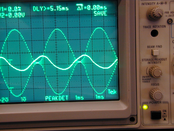
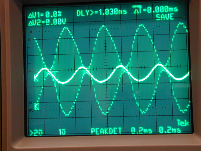
The Ranger has
excellent audio with
no changes except
the value of a few
coupling capacitors.
Triangle wave
response
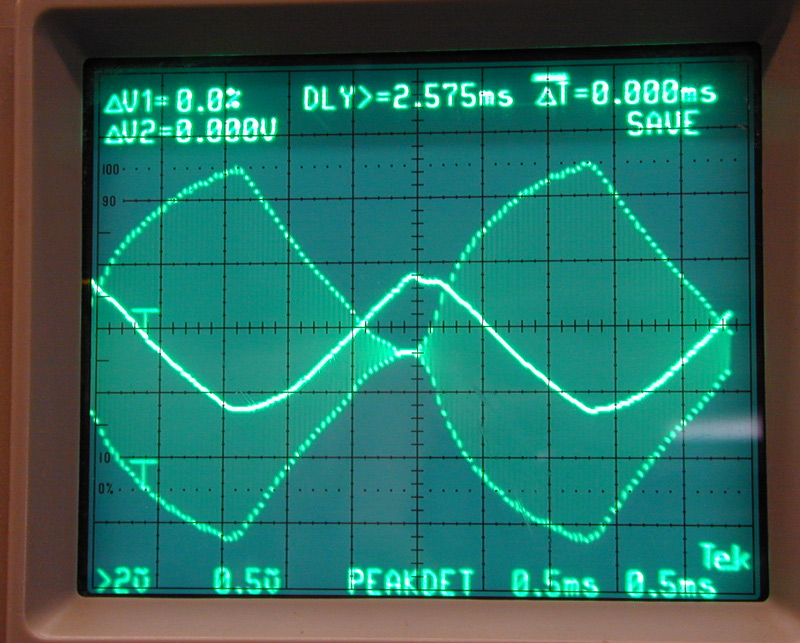
The line trace is
the audio at the
gain control pot.
The envelope is the
RF output waveform.
The Ranger
closely replicates
the waveform
applied.
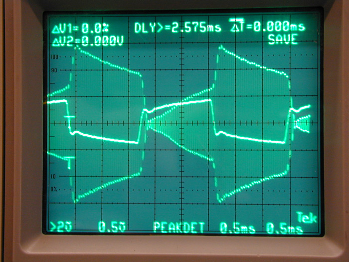
Square wave
response is also
quite good. The sag
of the top is caused
by low frequency
response starting to
roll off below 200
Hz. The slope left
or right on the
rising and falling
edges is caused by
the rolling off of
high frequency
response rolling off
above 3500 Hz.
Again the single
line trace is the
audio at the audio
gain pot, R21.
Pictures
of my Valiant and
its waveshape.
SPICE
simulation of a
minimal modification
improvement to
Ranger and Valiant
audio
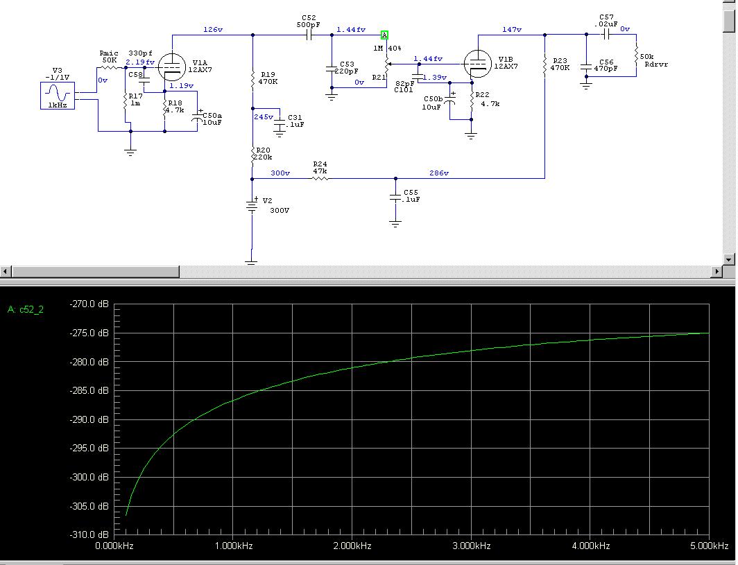
Original response
at anode of V7A:
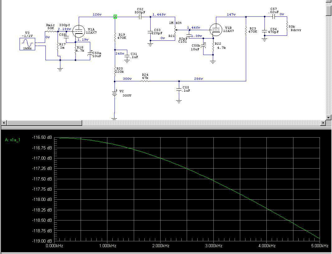
Note the rolloff
is only 1dB at 3000
Hz.
C52 produces the
following slope:
Below is
frequency response
at anode of V7B.
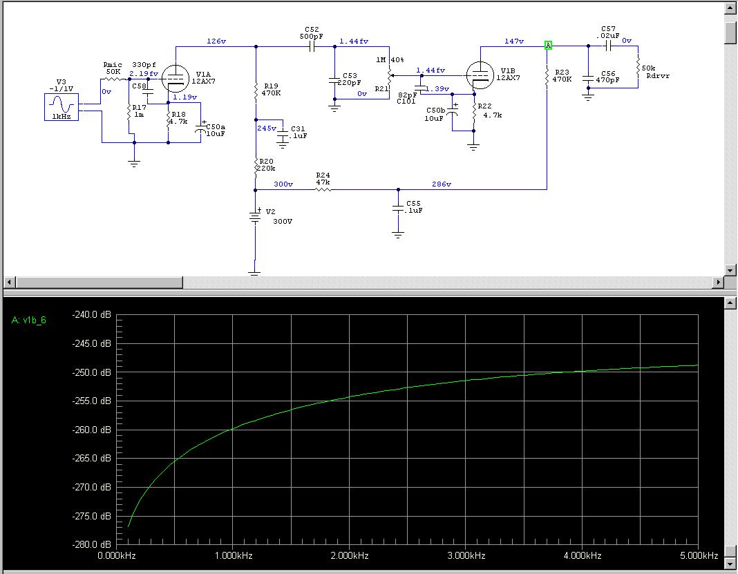
Note the large
low-frequency
rolloff. Rolloff is
from -252dBv to
-267dBv or a bass
loss of 15dB. This
was done
intentionally to
peak the
QRM-and-noise-cutting
high frequencies for
DX work.
Note how very
little C57 affects
the audio curve in
the sweep below.
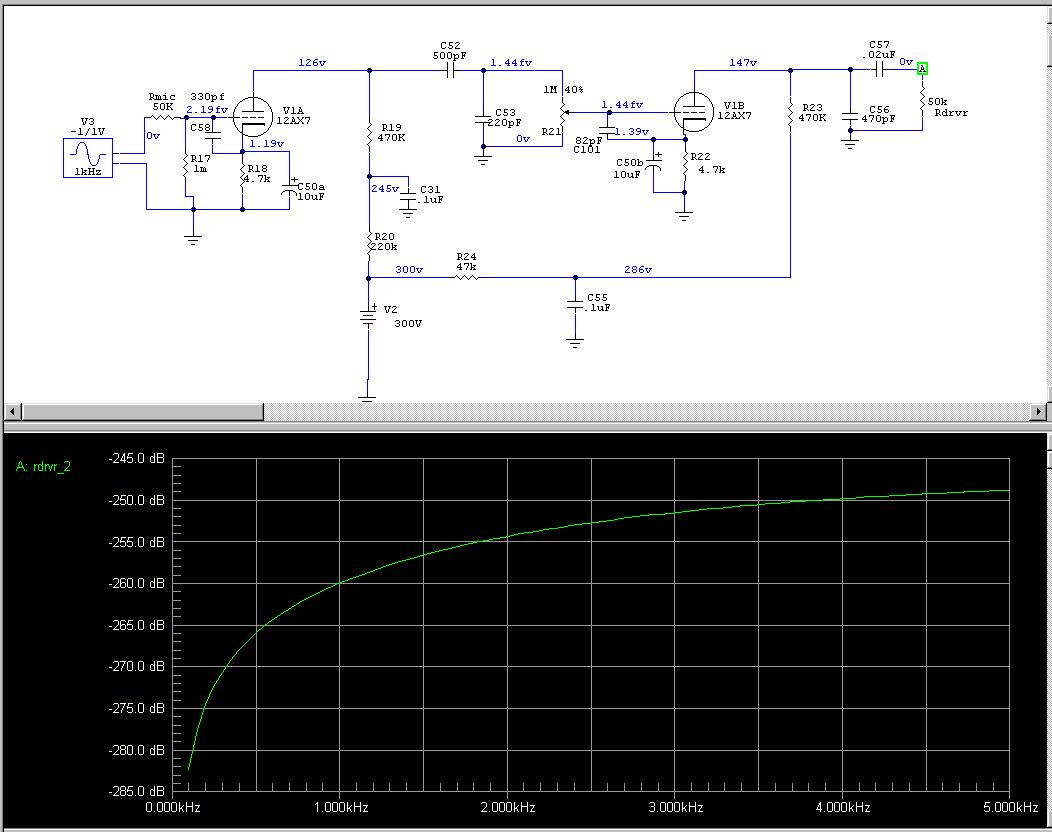
Frequency
response slope is
almost exactly the
same on either side
of C57. C57 is large
enough.
Changing C52
Only
Overall response
when C52 is changed:
*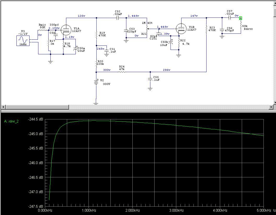
The graph above
is 1/2dB per cross
line. Overall
response actually is
quite good when only
C52 is changed.
Response falls
within about 1/2dB
from 200Hz to
5000Hz. Expanded
view of C52 mod
result:
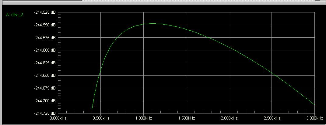
Between 400Hz and
3000Hz there is less
than .2dB variation!
All this from
changing only one
capacitor in your
Ranger.
-244.720dB @
400Hz
-244.545dB @
1150Hz
-244.705dB @
3000Hz
This will give
excellent sounding
full audio without
excessively taxing
audio transformers.
At the same time
your Ranger is
preserved, it isn’t
all hacked up with
dozens of changes
that produce
insignificant
results.
The old timers at
Johnson weren’t that
stupid after all,
were they? I’ll bet
they did the math
when they picked
parts.
 as as
of 1800Z on 2005 Dec
26
|