|
Related articles at
Balun Test
contains model of “perfect” dipole currents.
Sleeve Balun
shows how a sleeve adds impedance, useful for VHF and higher baluns
Receiving Common Mode
Noise shows how lack of a balun can contribute to system noise (it applies
to transmitting antennas as well)
Longwires, Verticals,
and Baluns shows how unbalanced antennas can have similar problems
Transmitting baluns
on testing transmitting baluns
Occasionally errors are made regarding core selection. This especially
includes baluns, where on occasion some very strange ideas surface. One rather
odd but somewhat popular idea is that adding a mixture of core types will allow
both high power operation and high choking impedance in baluns by slowly
reducing current through a balun. Other misleading claims are that extreme
values of core ui, such as values in the 10,000 or higher range, are necessary
on 1.8 MHz and higher. Other ideas tend support use of excessively low
permeability cores for the same application.
When I recommend a core, the material selection is always based on actual measurements
with proper test equipment on a bench as well as in the actual end-application.
Core Material
I mainly use 73 material for receiving applications in LOW POWER
applications between
.1 and 30 MHz. 73 and similar core materials generally minimize the turns count
required without inducing excessive loss. One of the best indicators of correct core
selection is looking at the turns required. You’ll notice most of the
transformers I use have only one or two turns for every 100 ohms of impedance.
My 75 to 450 ohm Beverage transformers, for example, only require two-turn
primary and 5-turn secondary windings. A low “turns count” is a good indicator the correct core
size and core material is being used.
For high power applications at HF it is often necessary to use lower permeability cores.
There are two reasons for this:
- Lower permeability cores generally are available with higher curie
temperatures. They operate at high temperatures without losing their
magnetic properties.
- Lower permeability cores have higher Q (lower loss tangent) at a given
frequency. This means a larger part of the impedance is associated with
lossless reactance rather dissipative
resistance. They turn a smaller percentage of power into heat, and that is
very important at high power levels.
Permeability changes with frequency. As frequency is increased from
zero eventually core impedance peaks. Above the frequency where impedance peaks the impedance of the core (and the
effective
permeability) actually decreases.
A downward slope in permeability with increasing frequency is useful for controlling
impedance in broadband
transformers, but we should be careful to avoid excessive slope. Excessive
initial permeability can easily move the operating area too far out
on the downward slope of impedance.
A transformer or inductor operating on the downward slope of a high ui core requires
extra turns to maintain critical impedance and often requires more turns than a lower ui
core. The upper frequency limit will decrease, and
this may reduce useful bandwidth in the desired frequency range.
Using excessive initial permeability means winding becomes more tedious (it
takes more turns). The wire has to be smaller and more fragile to fit a given core
window. Temperature stability is often reduced while losses increase over an optimum
core material selection. In addition, stray capacitance increases
needlessly, reducing bandwidth and increasing unwanted stray coupling.
Do NOT pick cores solely by considering initial mu, since that value is taken at dc.
You should consider characteristics measured at the
operating frequency!
Always remember this general guideline. Les wire length (as long
as winding impedance is sufficient) results in better transformer bandwidth. The best designs place maximum conductor length INSIDE the
magnetic core window, and
minimum conductor length OUTSIDE the core window.
Heating
At higher power levels, it is necessary to
move to lower loss tangent and higher curie temperature materials like 65,
61, or (in extreme cases) 43 materials. Even a fraction of a dB loss produces significant heating in small cores
when power level is in the kilowatt range. The loss DIFFERENCE in
non-resonant applications between lower and high ui ferrite cores isn’t significantly different, but
heating can be much
less!
We often assume heat means a core is very lossy or is “saturating”, but this
often isn’t true. We must consider the power level, duty cycle, and
ability of the core to dissipate heat and look at the full picture.
Very small cores, such as small thin .5
inch diameter cores used on bead-type choke baluns, can only dissipate a
fraction of a watt in open air. It sometimes helps to put temperature in
perspective by visualizing how hot a 60-watt light bulb runs in normal
operation. When we consider the core’s size, it usually has significantly less
surface area than the bulb. The core also has poor thermal conductivity, and is often stuffed in a container
preventing any type of air circulation.
Consider the construction of a typical bead balun, enclosed in PVC and heat
shrink tubing. As little as 20 watts dissipated out of 1500 watts can produce
damaging heat in tiny beads enclosed in a PVC tube. 20 watts out of 1500 is less than 0.1dB
loss, yet it overheats the core!
The problem is almost always a
heating problem, and not a core-loss problem. It is almost never core saturation, unless
the core is subjected to very low average
power and very high peak power levels. It is best that we worry about heat and
the number of turns we use, not actual power loss, when selecting a core.
Core Style
Soft-iron cores (soft magnetically) increase inductance because they increase
flux density near a conductor for a given current. With only a small
amount of flux “concentration”, there can not be a large increase in
inductance or impedance. We need a significant increase in flux to have a
significant increase in impedance.
The area outside the core window does NOT have a closed magnetic path
surrounding the conductor. The
presence of the core has a minimal effect on impedance of any conductor area outside the core window.
Most of the flux from external wires is in air, rather the core. With only a portion of the flux
surrounding the outer conductors cutting the outer layers of the core, the useful
impedance contribution of wire outside the core window to system impedance is minimal. Conductor
length outside the core window mostly adds unwanted stray reactance and leakage
flux. If we MINIMIZE the wire length exposed outside the core, and we
generally have a more effective inductor, choke, or transformer.
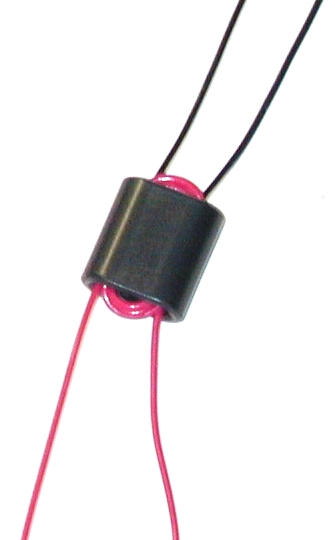
This effect can be easily conformed in a simple experiment using an
antenna analyzer. Connect a short wire across the output of an analyzer, and
measure the impedance. Lay a core against the wire, and observe the very small
impedance increase. Now pass the same wire through the core center, and observe
the large impedance change. This illustrates why the winding’s wire length on
the outside of the core is wasted, mostly contributing to undesired
effects.
Core Dimensions
The area inside the winding-window of a soft-iron (soft magnetically, not physically) core is cut
by all of the flux lines, and this area has a very large effect on
impedance. The core concentrates the
magnetic flux surrounding a current-carrying conductor into a very small area,
and the thickness of the core moving away from the area of the conductor very
rapidly has less effect.
- The additional impedance caused by placing a core over a conductor or
conductors is almost entirely proportional to the core’s
internal length (window depth) paralleling and surrounding the conductor
or conductors.
- The core diameter or
radial thickness only has a small effect on impedance.
Doubling the core area parallel with a conductor roughly
doubles winding impedance. The same is NOT true for an increase in core wall thickness,
core thickness barely affects impedance.
I prefer binocular cores for most low-power applications and side-by-side
stacks of cores (making a large “binocular core”) for high power
broad-band applications. This type of core arrangement
almost always minimizes the amount of conductor hanging “outside the
window”. With very little conductor hanging “outside” the core window,
there is less “needless” wire adding undesired stray capacitance and series
resistance. For a given core material and impedance, conductor length can often be reduced to
about one-third of a similar impedance choke (or transformer) using a conventional
single-hole core or single stack!
Low Power Measurements
Phase Inversion and Choke Baluns
Some of my receiving system designs use phase-inversion transformers.
Phase-inversion transformers are identical to (and interchangeable with) choke
baluns or line-isolation transformers. For HF receiving applications, 73-material binocular cores
are wound with six passes of #26 twisted-pair enameled
wire. I use Fair Rite Products 2873000202 cores (about 1/2 inch square and 1/3
inch thick 73 material).
Here are measurements of a sample inversion transformer at 2.5MHz using
accurate (and fairly new) commercial equipment:
| Load Value (ohms) |
Loss (-dB) |
Phase Error (degrees deviation from 180) |
| 100 |
~ 0 |
<1 |
| 33 |
~ 0 |
-1.2 |
| 10 |
0.2 |
-2 |
This shows inverting transformer construction is good, since even a 10-ohm impedance
load works well!
Beverage Matching Transformer
Sometimes I use designs for a long time, and forget how I decided they were
OK. I recently received an e-mail questioning the number of turns in my Beverage
transformer design, so it seemed like a good time to re-confirm the design.
I retested a 2:5 turn ratio transformer using a single FairRite Products
2873000202 core (about 1/2 inch square and 1/3 inch thick 73 material) two different ways on a generator/
network analyzer/vector impedance test set.
Total loss of two back-to-back transformers was .84dB at 1 MHz increasing, not
decreasing, linearly to .98dB at 30MHz. The actual transformer loss would be
.42dB at 1MHz increasing to .49dB at 30MHz.
Doubling turns increased the attenuation slope. While 1MHz loss decreased to
.69dB per pair, 30MHz loss increased to 1.21dB. This was for a PAIR of
transformers connected in series to make a 1:1 transformer. This of course
removes mismatch losses, so it is twice the real transformer loss. Actual loss
would be .35dB @1MHz increasing to .61dB at 30MHz.
Measuring a second way, I terminated the transformer in 470 ohms. Loss
measured .65dB at 1MHz when mismatch loss was included. Since receivers have
wide ranges of input impedance, any mismatch error might help OR hurt actual
system loss. Factoring out mismatch loss the second measurement indicated about
.53dB 1MHz loss with the original 2-to-5 turn transformer and .43dB with twice
the turns.
Every measurement has tolerances, and the two different methods do provide
different losses because measurement errors affect results differently. Still,
it is safe to say doubling turns has a negligible effect on 1MHz loss (which is
around .45dB).
|