|
Transmission Angles
Centering the transmission is reported to be necessary. This
is an analysis of how centering affects gear alignment inside the transmission.
First, let’s look at what Tremec says. As of March 3, 2015,
this is all they say:
Q: How do I index the bellhousing, and why is it important?
A: To say you have an improperly indexed bellhousing is also to say that
your transmission is improperly aligned with the engine in front of it. What
this means is that the input shaft is not sitting true into the pilot
bearing, which can cause a long list of transmission-related problems; as
small as hard shifting or as big as total product failure. We are currently
working on putting together our own online installation guide to address
these issues. However in the meantime, there are several articles online
that explain the principles of driveline angles and how to properly set
them. Here is a link to get you started:
http://www.carcraft.com/howto/91758/index.html
The link isn’t even a good one. It is for rear ends.
I found this link:
http://www.hotrod.com/how-to/transmission-drivetrain/ctrp-0404-bellhousing-alignment/
In it, they say:
As you are measuring a circle, remember misalignment is one half of the
indicator reading. It’s best to always use the same location spots as you go
through measuring and fitting. The Lakewood personnel who showed us how to
do it marked the 12:00 and 6:00 locations with their readings. If the
reading is within tolerance of 0.005 after checking twice, you’re ready to
go racing.
Here is an article that appears to be loaded with
“dramatic bologna”.
http://camaros.org/bellhousings.shtml
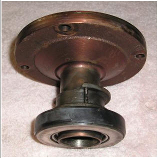
In that article, they claim:
As an example of the damage that can result from misalignment, the
photo below shows a seized throw-out bearing stuck on the transmission
input shaft bearing retainer. In this case, the bellhousing to block
alignment was out of tolerance by 0.014 inch. This misalignment created
excessive stress on the pilot tip of the input shaft, which eventually
fatigued, broke off, and allowed the transmission input shaft to wobble
extensively around in the crankshaft. This resulted in tremendous heat
sufficient to cause the throw-out bearing to weld itself to the bearing
retainer. When this happens the vehicle is not driveable at all. Note
the broken ear on throw-out bearing from trying to remove the
transmission.
|
I’ve seen similar misdiagnosis is electronics, where
components fail. It is common when something breaks, and someone with good
intentions looks for anything at all wrong to blame. A misdiagnosis like this is
actually very common. (As a manufactured product engineer I have to look at and
analyze equipment failures. Around half of my work deals with solving OEM
reliability or field failure problems.)
The truth is, we really can’t know why the input shaft
tip broke. What we do know is the angle misalignment was around, and probably
less than, 0.15 degrees error.
Let’s look at what alignment means.
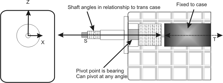
A rough drawing of a typical transmission follows:

There is an input shaft with dimension A that connects to a
gear inside the transmission. That gear has a large helical gear that drives a
cluster gear that sits next to the input shaft, and the input shaft has small
radial tooth set on the end that drives a straight-through slider connection for
direct drive.
The input shaft floats inside a sleeve. The input shaft is
supported by a bushing in the crankshaft end center, and a second support by a
roller bearing race at the transmission front. The crank center pilot bushing or
bearing and the transmission input shaft bearing (which allows some small
tilting angle) are ONLY supports for the input shaft. The alignment of the crank
bushing and the transmission input bearing center, along with the flatness
of the transmission case to the crankshaft centerline, set the
angle of the input shaft to the cluster gear (cluster gear tooth mesh) and the
input shaft to main shaft alignment.
The AMOUNT of angle change and the physical movement,
as a percentage of external misalignment, depends on the distance from the pilot
bearing to the transmission input shaft bearing, and the distance from that
bearing to the mating gear or slider.
I’m not going to get into the claims of great damage by small
alignment errors, but rather focus on how this works. The reason for this focus
is to let YOU decide if everyone measures things that actually mean
anything, or that guarantee alignment.
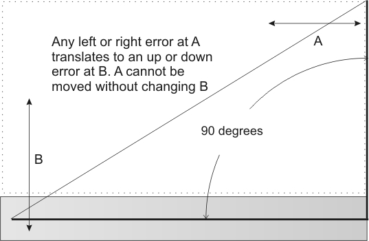
Alignment is important three ways. The Z and X axis (normally
checked), and the crankshaft centerline to transmission case front angle (which
should be exactly 90 degrees) that is almost never even considered
1.) The transmission input bearing is a fulcrum point for
alignment issues for deflection in inches
2.) The transmission case face to crank centerline also
directly affects alignment. The alignment degrees should be exactly 90, and the
angle error is NOT stepped up or down by shaft lengths
3.) The crank pilot centerline to transmission input bearing
center determines distance alignment errors through a lever action, like a
teeter totter! Any error is stepped down by the ratio of shaft length outside
the input bearing to contact point of the input shaft inside the transmission
4.) I will assume the transmission is constructed perfectly
inside, without any alignment error internally and it holds gears and the
transmission holds internal shafts perfectly rigid in alignment (good luck on
this with hundreds or, depending on the gear and the engine, many thousands of
lb/ft torque distorting things!)
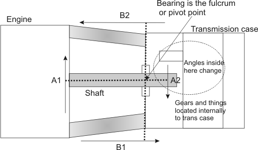
Crankshaft to bellhousing transmission center location errors
Any centering error of the shaft or transmission, measured at
the bell, is translated by the ratio of shaft outside the transmission bearing
center (B) to length inside the transmission at the contact point to F.
If we look all the way at the end of F, it might be dimension C. In
this example the very worse case alignment would be C/B * error = actual
internal error
Let’s say we have .005 inch error outside in transmission
centering, and everything else is perfect. The internal distance error would be
.005* (C/B) = .005 * (3.7/6.8) = .005*.544 = .00273 inches.
The degree error would be the same. If we had a .05 degree
error outside, it would be a .05 degree error inside. Angular error is not
changed or modified by lever action.
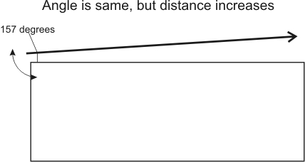
This works like a teeter-totter, or a triangle or
parallelogram geometrically. With a fixed degree error, a long physical distance
between points means far
more than a small distance angle error. The distance error can also be
multiplied or divided by lever ratios to the pivot point or fulcrum. Think about
it this way; let’s say we are installing a long fence. We measure two points 120
inches apart, and make a 1 inch mistake. At 240 inches, the error is the same
number of degrees but becomes 2 inches.
Looking at the face, shaft, and bellhousing we find:
This is why the transmission face distance error to the
crankshaft center line (through the bellhousing) means far more than the
centering of the transmission in the bellhousing hole (or input shaft centering
to the crank center). That angle should be 90 degrees, but is so difficult to
measure accurately I doubt anyone does it. Measurement error would probably
exceed machining errors because almost no one can measure
small right angle errors accurately. I have machine equipment, and cannot
measure .05 degree errors. If dust gets on the surfaces, or a hair gets in the
way, the error can be .002 inches or 0.2 degrees or more.
Angles and Distance
Putting size into perspective, the average thickness of a
human hair is 0.004 inches.
Let’s say the input shaft tip is 6.8 inches forward of the
input bearing center, and we measure a bellhousing hole error of .005 inches
down. This crank centerline error shifts the transmission bearing down .005
inches to the crank, which is the same as lifting the input shaft nose by .005.
This moves the input shaft gear down .005 * C/B or .00272 inches at the
furthest point of the input shaft. If the input gear was 1.5 inches
forward from the end where the slider teeth are, the start of the gear would
shift down .001618 inches, or less than half a hair.
Now let’s say the locating hole center is perfect, and the
transmission top is .005 inches back from the shaft centerline. This .005 inch error
is equivalent to moving the input shaft tip up .005*B/D = .01236 inches. This
.005 inch backward move in relation to shaft centerline position is .01236/.005
= 2.47 times the error caused by hole centering on the crank. This means if the
paint on a perfectly machined bellhousing is .005 inches thicker at the
transmission top edge, it is like having the hole center .01236 inches off.
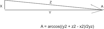
Angle A is the arccos (or also written cos-1) of (y squared + z squared – x
squared ) over 2 times y times Z For .005 inches deviation measured over 6
inches, the angle is: cos-1 (6^2+6^2-.005^2)/2*Z*Y = 71.999975/72 = cos-1 of
0.999999653 = .047746469 degrees.
If we offset the bearing centerline on a six inch long shaft by .005 inches,
the degree error is less than .05 degrees. A .005 inch error measured over 6
inches spacing causes a degree alignment error of a little less than 0.05
degrees.
Now you see why I am starting to have a problem with, or at
least be very skeptical about, the idea that measuring hole center is
meaningful.
Since we cannot measure what matters, we measure
something we think (and everyone says) solves the problem. We make something to
be a problem, we
ignore what is probably a much larger problem source, and we fix the problem we
invented.
I’ve been installing stick shift transmissions for about 40
years or more, and never measured the locating hole center one time.
|