|
Related Pages
Splicing Wires
Receiving Antenna Systems
My History With Beverages
I originally began experimenting with long, low, wire antennas in the 1960’s.
Even though I had a working mostly homebrew station, I now realize I had only a
small
idea what I was doing, and almost no understanding of what made antennas work.
My entry into Ham radio was
from modified broadcast radios, and the very active 160-meter mobile group in
Toledo, Ohio. I always thought the longer the antenna, the better the “pickup”. was fascinated
by the distant AM broadcast, lower shortwave, and 160-meter signals heard with
long antennas. My early antennas were nothing more than hundreds or thousands of
feet of very thin magnet wire, strung over tree limbs and along telephone poles
(which had steel climbing pegs), all through a typical crowded 1950’s suburban
neighborhood. Unfortunately my early experiments were hampered by lack of room. Thin magnet
wire, unwound from early-radio speaker field magnets, strung in the middle of
the night through a crowded suburban neighborhood across neighbor’s small lots, doesn’t stay up long.
In the early 1970’s, I moved to a house
with several acres of woods. The soil was a very wet, sandy, black loam. A
neighbor just north of me, W8FPU (Parker) was actually working a couple of VK’s
on 160-meters, something very rare at the time. Using information from a
series of engineering lectures by John “Jack” Kuecken (now SK) and correspondence with Stew W1BB,
I installed my first “real” Beverage antenna. I
was delighted to find a large improvement in weak-signal reception from very
simple, inexpensive, easy-to-install wire antennas. Eventually, that system evolved from a few long
single wires to a two-wire reversible system. The two-wire system used two Beverages, oriented 90 degrees
from each other.
This gave four direction coverage. That system, with the addition of an in-phase
and out-of-phase combiner, evolved into a forced-null system using just two
reversible antennas. This was before binocular cores were available, and
ferrite beads were just appearing. At the early date, I used a series of 73-mix
beads to make my transformers, even publishing a few articles in small
newsletters.
I continued to improve or refine my Beverage antennas over the years. Virtually all of my Beverage antennas now are arrays of
multiple Beverages, not just single wires. While my large circle arrays of
verticals, or broadside endfire arrays of verticals, are about even with two
long phased Beverages, the Beverage arrays are simpler systems. Arrays of
broadside Beverages
remain my primary DX receiving antennas for the lowest bands. There isn’t any
other receiving antenna that
is as simple, as easy to construct and maintain, and as foolproof as a Beverage!
The only
significant Beverage disadvantage is the
long physical length
required, and maintenance of a very long
antenna. If we want significant directivity, Beverages (like all long wire
arrays) require a great deal of space .
Testing and Comparing Antennas
I work a little different than many or most people when experimenting, always
A-B testing and comparing antennas over time. This is partly because a newer,
bigger, or better looking antenna always feels better. Even before something is
used, especially if the “something new” involved effort or expense, we can
“like” it and become emotionally invested in it. We want something new to work
better, so we look for everything “good”.
I
credit a 7th and 8th grade science teacher for educating students about this
phenomena. Early
in school, a science teacher at Olney middle school in Northwood, Ohio
demonstrated how easily and often false conclusions are reached, based on
feelings about results
or past performance memory. One year of science with Mr. Kohler, when I was 12 or 13
years old, changed how I look at many things in life. Because of Mr. Kohler, I
almost always retain a reference or control, try to use direct measurements of
what I actually want to know, and use multiple methods when possible. Mr. Kohler
demonstrated how easy it was to reach false conclusions, unless we use valid
measurements.
Most antenna myths
and misconceptions, many making it into print in articles, come from repeating feelings
or unsubstantiated claims, or
are based on improper measurements or models. I’ve seen comparisons years apart,
going on memory of how signals were on some other antenna that was long gone!
I presently have a great deal of room, with wiring in place to install
multiple antennas, and reasonably good test equipment. This allows installation of multiple
antenna systems at the same time, which allows direct comparisons over time, as
well as measurements. I constantly refine antenna systems by comparing
systems against each other for extended periods of time, usually more than a
year.
My Installation
W8JI’s Beverages
Even though I use engineering tools (books and models), I always compare and
measure actual working systems (in multiple ways if possible). My station has a convenient switching system,
allowing instant
comparison of antenna systems. When an antenna system is almost never better, or
evolves to almost never being used because other system is better, I abandon that
system. I keep the better-working systems, and try to find something better
still. I presently have over thirty Beverages in three different
clusters of arrays, the end result refined through years of measurements and A-B
comparison testing of
systems.
User interface is important when comparing antennas. Since the early 1970’s,
I’ve used push-button antenna controls. Push-buttons allow instantaneous
back-and-forth changes while testing, without needlessly distracting the
operator. Push-button controls are good for contesting, and good for
experimenting.
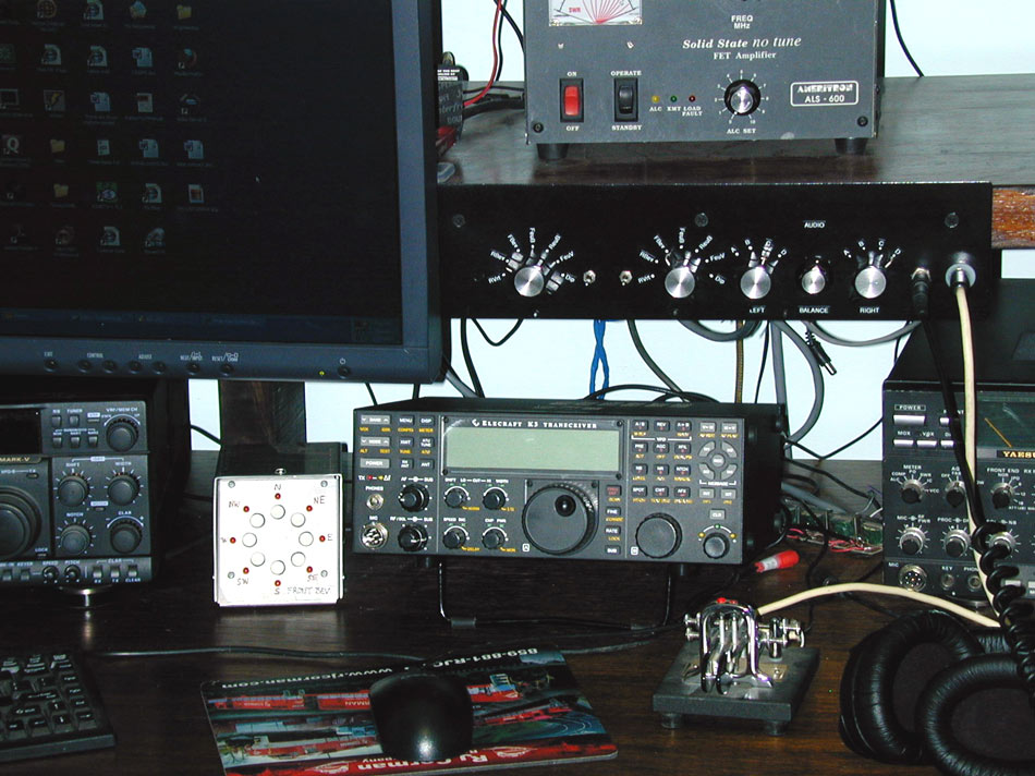
This control
panel selects
antennas for each
receiver in the K3.
The far left switch
is for the main
receiver which goes
to the left ear, and
the next switch left
goes to the sub
receiver which is
the right ear. I have seven primary antenna group selections available.
The K3 is the
only standard
transceiver system
offering true
diversity. Other
receivers advertise
diversity reception,
but performance is poor. As a general rule, the receivers are not identical, and
audio phase is not locked!
To have true
stereo diversity, each channel must have an identical, or nearly identical,
receiver. All frequency control and bandwidth adjustments must
track.
The small, silver, push-button box on the desk selects
directions. In the normal case, I lock all antenna group directions to one box.
For contest use, directional control of antenna groups can be independent,
through use of multiple identical control boxes.
My system has a special locked-position for Europe antennas, since they are
the most frequently used antennas. Operators can lock their “ear of choice” to
Europe, while scanning any of eight directions on the other ear, using the push-button
directional control.
Types of Beverage Wire
Insulated or Bare Wire
I
occasionally hear or
read claims that insulation prevents charged droplets
of water from making an antenna “noisy”. I’ve never been able to
verify that claim, either in A-B tests of actual antennas, or through planned
experiments. Other reports, many from reliable sources, also seem to discredit
the claim that charged droplets striking the wire cause noise.
One of my experiments was to charge a stream of
water (against earth) with an extremely high voltage supply, and spray the
charged water on a wire.
Other than corona noise from sharp points, the type of wire
(bare or insulated) made no difference
at all in “noise”. The
charged water droplets were not
discharging into the wire
like hundreds of random charged capacitors, they generated no
detectable noise at all. This is really what we would expect, if we consider that each drop
contains only a very miniscule amount of charge, and also has nearly perfect
insulation (distilled water is a very good insulator).
Controlled and general observations support the idea
that corona actually cause
precipitation static, rather than charged individual droplets
striking the antenna.
In Ohio, my long Beverages stretched
across open farm fields. Snow would whip across the fields, rain would pelt the
wires, yet insulated wire and bare wire Beverages, running in the same direction,
always had about the same noise level. Beverages that picked-up corona (or “p-static”)
noise were always near or aimed at tall towers. With corona noises sizzling at
40-over-nine on my tall towers, Beverages (and even small “magnetic”
loop antennas) aimed at my towers or near my towers would
“hear” the same precipitation noise.
The same was true for tower-mounted antennas. The largest noise problems came
from antennas mounted high on towers, and generally were with antennas that had
“sharp” ends jutting out in the air. Lower antennas, even those of
identical construction, were either significantly quieter or totally free of
precipitation static. This effect was reported many times by contest operators
and DX’ers with stacked antennas. They universally switch to low antennas to
eliminate or reduce p-static, even though the same moisture is hitting the
lower and upper antennas. This strongly indicates precipitation static
is from corona discharge, and not from charges in each individual
drop of moisture hitting the antenna.
After my move to Barnesville, Georgia, hook-up wire was
pressed into service in my first group of temporary Beverages. As non-insulated
conductors in more permanent antennas were added, there wasn’t any observable change in inclement
weather noise. As before,
antennas nearest or aimed at
my tall towers picked up
p-static noise. Antennas located away from the towers remained free of
precipitation static. Each was true, whether bare or insulated
wire was used.
There is often some element of fact behind rumors. Insulated wire may reduce
noise, if the insulation reduces corona discharge. Insulation can prevent St.
Elmo’s fire from narrow points. Also, insulated wire might result
in more consistent performance. If a substantial part of the
conductor is in contact with unwanted resistive paths, such as wet brush or tree
branches, insulation can reduce leakage losses and attenuation. But we are
probably better off just trimming back any substantial foliage in
contact with the antenna wire, and using air insulation.
In my experience, directly comparing various receiving antennas at the
same time over many years, insulated wire has no major performance advantage.
It also has no significant disadvantage. Use
insulated wire if readily
available, but unless your antenna is in contact with soil or other conductors, don’t
go out of your way
to purchase insulated
wire.
Field telephone wire is sometimes used in
reversible Beverage antennas. Such wire is generally a terrible choice. I
measured a 160-meter band loss of around 2 dB per 100 feet with clean dry field
wire, and around 4 dB loss per 100 feet on 7 MHz. This means the
transmission-line mode of a reversible full wavelength Beverage, which supplies
the far end connection, would have a dry weather loss of about 10dB on 160
meters. Field wire, speaker wire, or zip cord has to be the ultimate in trading
performance for cost.
Type of Conductor
The most common Beverage wire types are single-conductor hook-up wire or electrical
wire,
electric fence wire, and specialized antenna wires such as copperweld.
The only
easily noticed differences between commonly-used wires are
in physical properties, such as ease of soldering, strength, and life.
I’ve generally avoided aluminum wire because of
connection issues, so I cannot comment on aluminum Beverage wire.
Copper wire is a good choice if supports are close,
and if it is readily available.
Pure copper wire lacks the
mechanical strength of steel-core wires, but is very easy to work with. It is
softer, making it easier to bend. Copper wire can be repeatedly scraped,
cleaned, and
re-soldered without worries about piercing a thin copper coating and exposing a
rust-sensitive steel core.
Copper wire is readily available, and relatively
inexpensive, in large quantities.
Copperweld wire is much stronger and has about the same RF resistance as 100%
copper. Like copper, it is easy to clean and solder after
it has been exposed to the weather as long as you are very careful to not scrape
through the outer
layer of copper. It is considerably more difficult to
work with than normal pure copper wire, any
small kink or sharp bend will
substantially weaken the wire. Be mindful how thick copper is. Many copperweld
wires have such a think layer of copper that current flows in the underlying
steel core on lower bands.
Steel wires like electric fence wire are strong
and cheap, but have some disadvantages. One disadvantage is rust. In middle
Georgia, common brands of electric fence wire last about 5 years before rust
becomes a problem. If an antenna is properly terminated, contrary to some internet claims and rumors, there is no advantage to lossy steel wires, such as electric fence
wire. If a wire is improperly terminated, adding loss to the wire will increase
F/B ratio. This is because the wire self-terminates through series resistance
distributed along the wire’s length. This effect can actually be measured and
documented, by observing current
taper along the wire.
Copper wire #16
| Feedpoint |
.996 amperes model |
1 ampere measured |
| 200 ft |
.971 |
.94 |
| 300 ft |
.903 |
.90 |
| 400 ft |
.885 |
.88 |
| 500 ft |
.850 |
.82 |
| 600 ft |
.819 |
.78 |
Steel wire #17
| Feedpoint |
.996 amperes model |
1 ampere measured |
| 200 ft |
.892 |
.92 |
| 300 ft |
.793 |
.86 |
| 400 ft |
.636 |
.78 |
| 500 ft |
.522 |
.70 |
| 600 ft |
.495 |
.64 |
Due to the close proximity with lossy earth, Beverages have substantial
current taper with distance. Current taper reduces available directivity,
because antenna areas further from the feedpoint connect through significant
attenuation. This undesired current taper is increased with reduced height, as
well as unnecessary antenna conductor losses.
Most fence wire I’ve found is cadmium plated, rather than zinc galvanized.
Using RF current meters, zinc or cadmium plated steel wire clearly shows
increased loss compared to copper or copperweld wire. I’ve measured about 60% of feedpoint
current remains (~4.5 dB loss) after passing over around 700-feet of electric
fence wire, and about 75% of current (~3dB loss) using copper-clad steel
wire of equal length.
Examining some opinions, we find steel wire viewed as offering a positive
performance benefit in F/B ratio. Common sense tells us the only way F/B
ratio is modified, is if the reflected wave’s amplitude is significantly
decreased. The only possible way steel wire can benefit noise level or F/B ratio
is if steel adds significant attenuation along the length of the antenna. At the
same time beamwidth, and any advantage caused by increasing antenna length, must
diminish. Steel fence wire would aggravate losses, and losses (and spatial
fading) already limit performance of extremely long Beverage antennas. In a very long antenna, the small additional
loss of steel fence wire would reduce performance.
In my Beverages, the important consideration is antenna maintenance. I use copperweld wire or electric fence
wire, because strength is a primary concern. With spans exceeding 200 feet, my
antennas need a large strength-to-weight ratio.
Don’t use welding wire! It is a very poor material choice. Welding wire has
poor conductivity, easily rusts, and as
with aluminum, can be difficult to solder.
Beverage Supports
There are claims non-metallic supports work better for Beverages,
but there is not the slightest technical justification for
using non-metallic
support posts.
The only requirement for the support is it must hold the antenna up, and the
support
cannot connect the antenna to ground. A metal pole with a small PVC stub for an
insulator is every bit as good as a non-metallic pole. Trees make good
supports, especially if you use nail-type electric-fence insulators designed for
wooden posts.
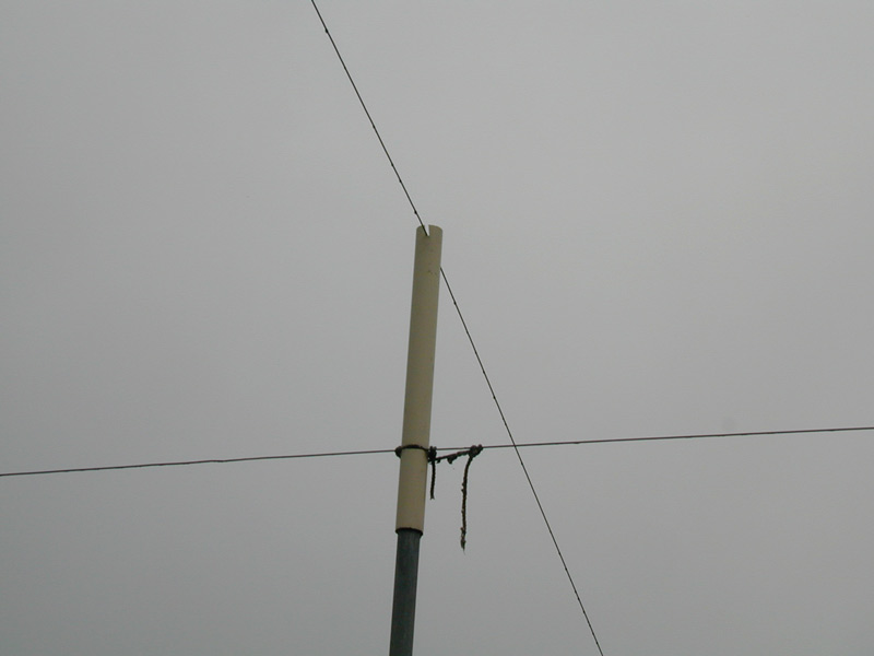
A typical
cross-over point in
my installation of
over 30 Beverage
antennas.
PVC is wedged
over the end of
standard metal
conduit. The PVC is
notched and sanded
smooth so the
beverage wire can
slip freely through
the PVC. String may
be required to hold
the lower wire in
the notch.
Physical
separation is six
inches to one foot.
I’ve never seen a problem allowing a wire to contact a branch, although
I do trim out the branches and avoid any contact with trees.
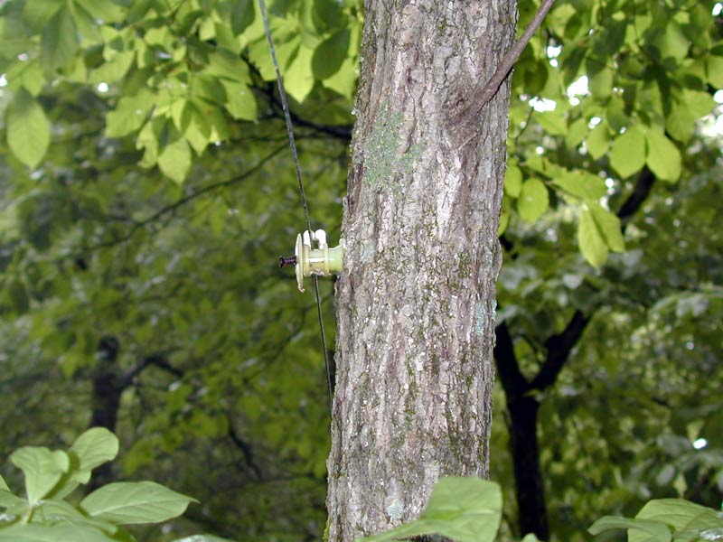
Notice the wire
floats freely
through the
insulator. This
allows a single
tensioning point,
and easy checking at
one point to see if
the antenna has lost
tension from a
break.
I never anchor or
wrap the Beverage
wire around
insulators, except
at the ends. I
always allow the
wire to “float”
through the
insulators.
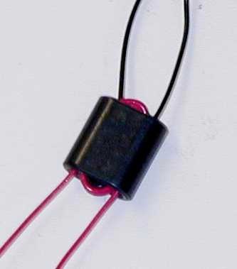
A wire often can be supported from
overhead, using a
strain or
compression
insulator:
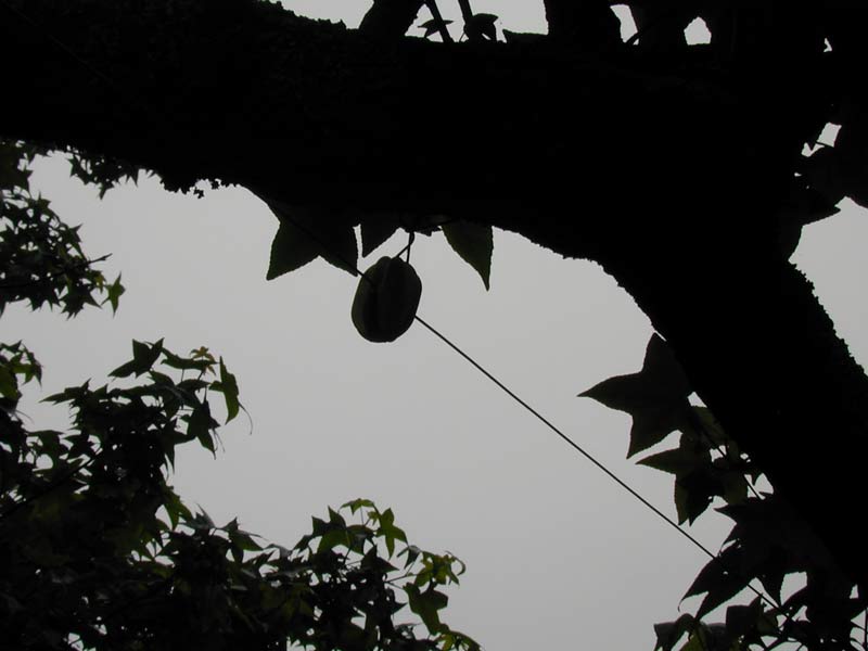
The standard
strain insulator
hangs from a branch.
The beverage wire
lays across the
insulator webbing,
fully floating. Only
the hanging wire
wraps the web.
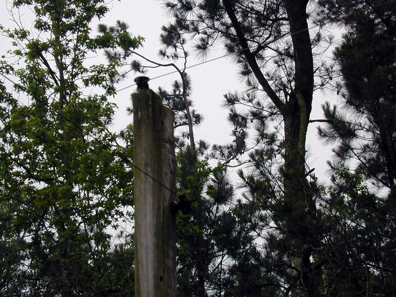
A wooden
cross-over support
post
For end supports, I use trees, pressure treated lumber, or landscaping
timbers. With a lot of tension, I backstay the poles to a dead-man (generally an
old brick) buried in the ground. When I set end-posts with my power auger, I
line the hole with copper flashing. The flashing becomes part or all of the feedpoint
(or termination) ground connection.
When
the wire floats
along the length
between ends, you can tension the entire antenna from either end. If anything
breaks the wire, you can see it at any point! A “floating” wire is
much easier to repair if it is damaged, because you only need release tension on
one end to splice the wire. Re-tension that same end, and everything is
restored.
It takes no more tension to support a 1000-foot Beverage with supports
every 100-feet than it does to support a 100-foot wire between two rigid
supports, but it is a much more difficult to break the longer
floating wire. A longer
“floating” wire will often take-up enough slack to remain up after
deflecting a large tree branch, where a shorter rigidly-anchored span will
almost certainly break
either the insulators or wire.
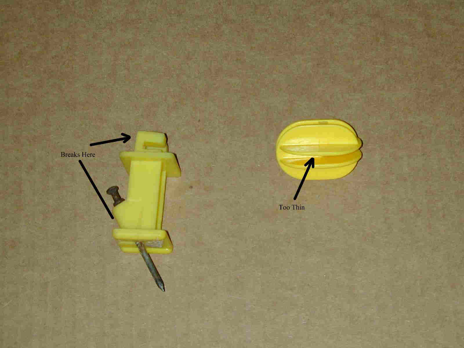
Beverage Insulators
If you expect a long-lasting antenna and have a long antenna, be careful when choosing
insulators! Some types of electric fence
insulators will not last long. The unreliable types of post insulators have two
square folds to hold the wire, a square shaped base, and nail through a small
molded plastic angle. The weak points of this insulator are the square retaining
tabs, and the molded nail tube at the insulator base. When this type of
insulator is mounted horizontally, the wire’s weight will stress both the molded
nail tube and a single tab. I typically find about 10% of the insulators fail
within a few months. After three years, the few dozen installed here have
virtually all failed.
Avoid these types!
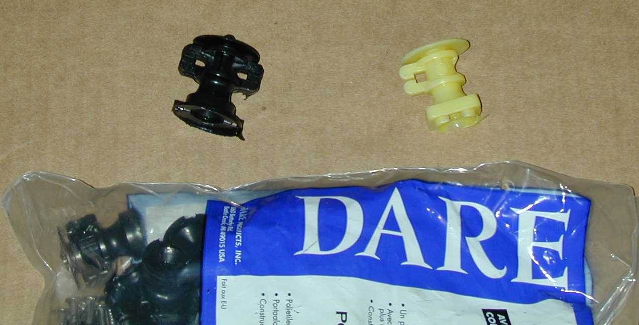
Round yellow or back plastic insulators with the nail going through the
center, like the examples below, are much more reliable post insulators
Ceramic post insulators may look great, but they do not allow floating the
wire across the insulator. Even if you do manage to find a ceramic insulator that allows floating the wire, the
ceramic will quickly wear away at the constantly moving wire. Avoid ceramic insulators, unless you
are prepared to “buffer” the wire through a UV resistant soft plastic
bushing!
Good end-insulators are becoming difficult to find. I always use compression
types, but the material has to be either ceramic or very thick plastic. Some
very thin plastic compression insulators will actually cold-flow and allow the
wire to pass through the insulation. This is particularly true with thin steel
wires that are tensioned over 25 pounds. Heavy-walled egg insulators are much
more reliable, and not subject to wire migration through the thin insulation.
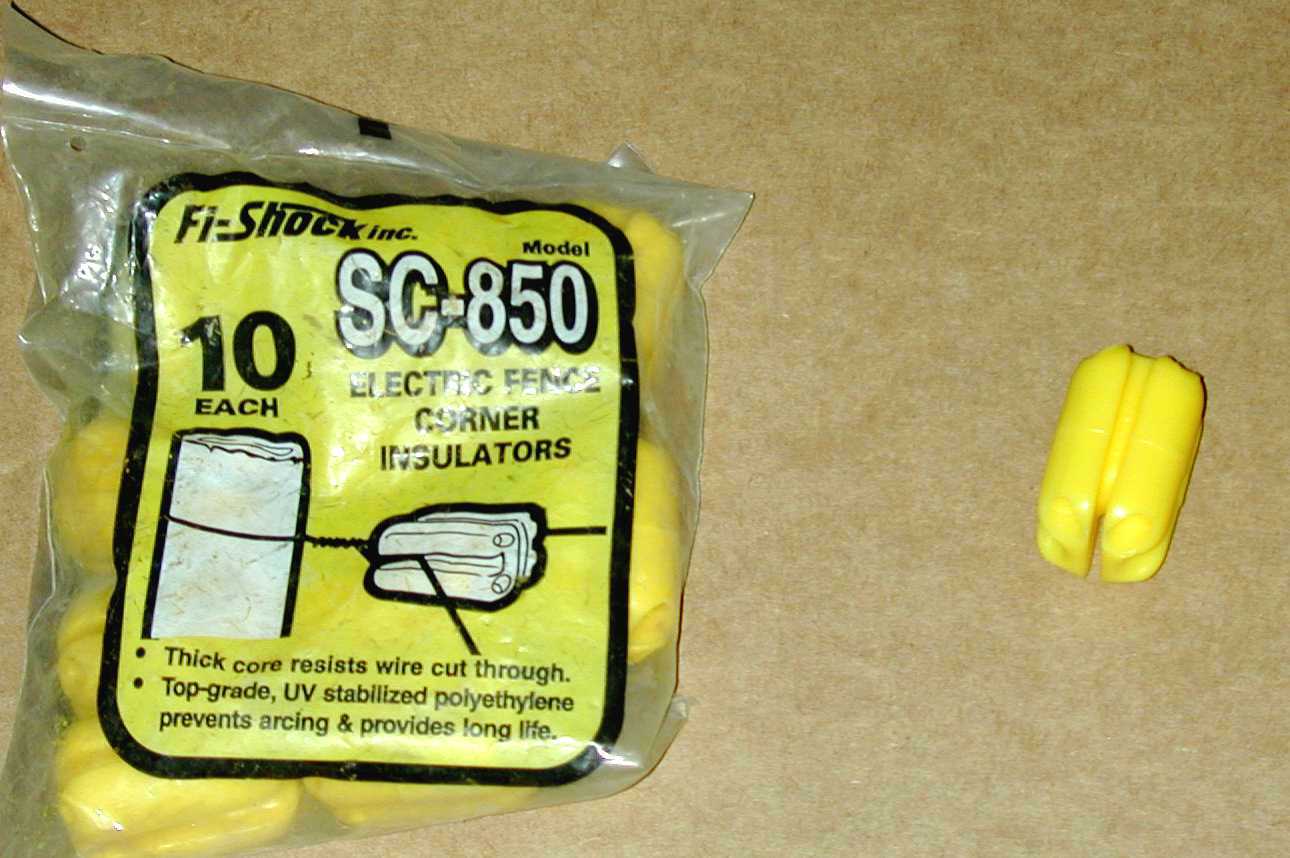
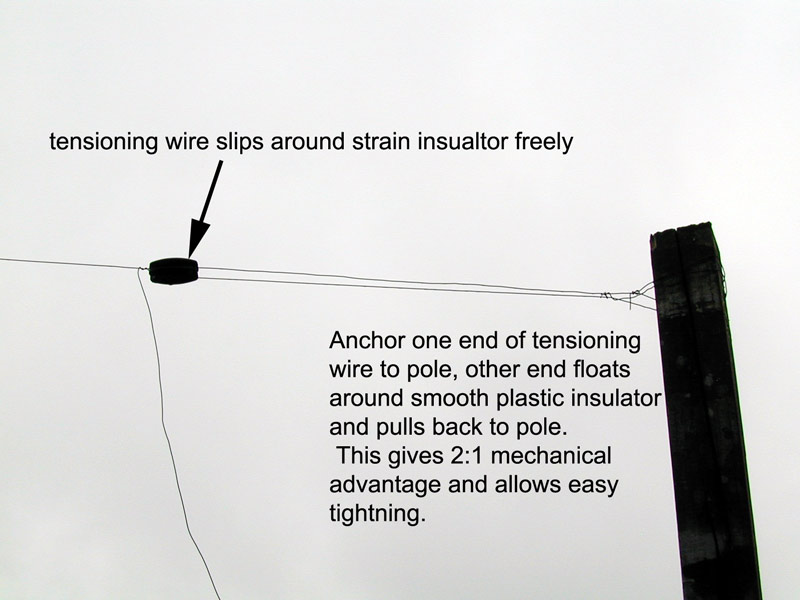
My favorite insulators are large these rather thick Fi-Shock yellow plastic insulators.
They are slippery enough to allow the dead-end wire or rope to loop over the insulator, and
create a 2:1 mechanical advantage when
tensioning.
Height
I’ve found very little performance difference with height, unless the
Beverage is more than .05WL high. As the height exceeds .05wl, performance seems
to be reduced. Small rolling hills or ravines also seem to make any
difference. Follow the contour of gradual slopes, and go straight across
ditches or narrow ravines without following the contour.
Sloping Ends
There really isn’t a logical reason to slope the ends of a Beverage. After
all, six-feet of vertical drop is six feet, no matter if the drop is over 50
feet or straight vertical.
Consider, for example, the K9AY or Pennant antennas. Both have sloped wires,
yet virtually all of the response is from the vertical slope of the wire in the
antennas. As a matter of fact, the actual shape makes very little difference in
the way each antenna works. Why would anyone, knowing how a Pennant or K9AY
works, think that a Beverage somehow magically breaks tradition and stops
responding to vertical signals in the wires when we slope them a bit? What
difference would it make in noise anyway, since the entire antenna responds to
vertically polarized signals?
There isn’t any possible way, including use of shielding or additional
conductors, to prevent the end-wires from having the very small effect they
have. Save yourself time and worry, and avoid a needless hazard. Just drop the
end-wires vertically right down to earth.
Multiple Antennas Crossing
Crossing of Beverages has little effect if they are not parallel or nearly
parallel. Try to cross at an angle of 90 degrees if possible. Even a few inches
of spacing is enough for right angle crossing. With shallow angles, assuming
they can not be avoided, increase wire spacing to a few feet.
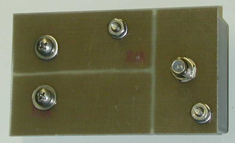
Transformers
Always use isolated transformers for feeding Beverages. It is cheap, simple,
easy insurance against unwanted common-mode ingress of noise and signals into
the antenna from the feed line shield. See the Common Mode Noise page for an
analysis.
I use 73-mix FairRite Products 2873000202 cores (about 1/2 inch square and
1/3 inch thick 73 material) in my transformers. These cores require a two-turn 50-75 ohm
winding. The high-impedance winding is 5 turns for 75-ohm cables (6.25:1 Z
ratio) or 6 turns for 50-ohm cables (9:1 Z ratio). Small insulated hookup wire
is actually better than enameled wire. The thicker insulation is much less susceptible
to developing shorted turns in rough service.
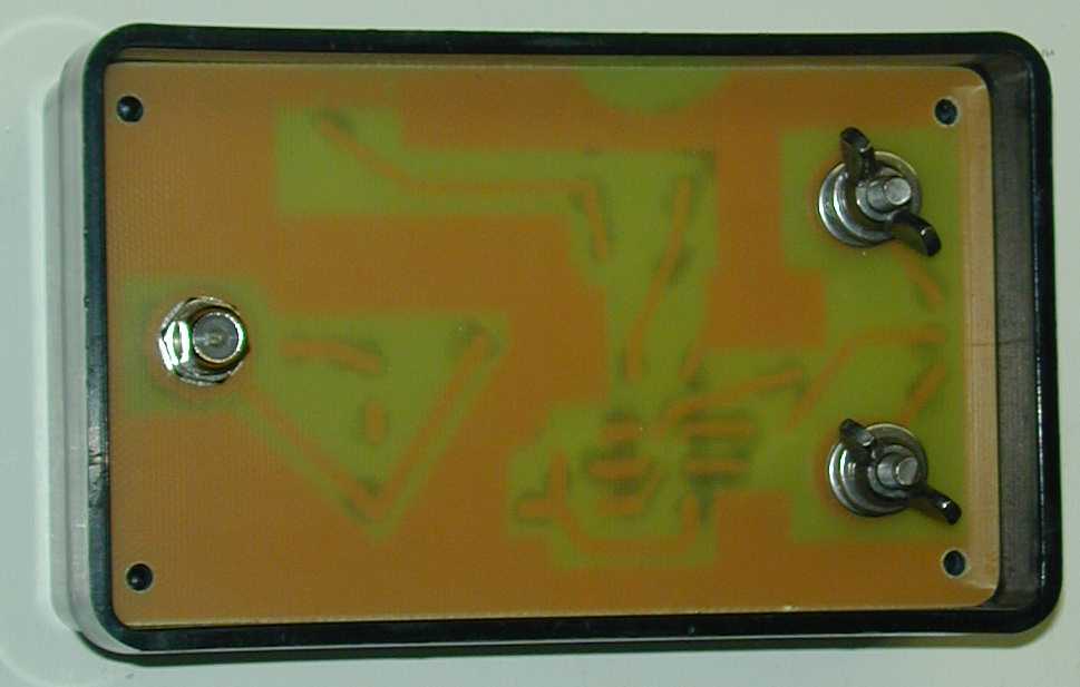
While my early transformers were waterproofed with Krylon and coated with
insulation foam, I have finally laid out enclosed transformers and terminations with
internal lightning protection. The transformer sections have F-fittings, and all use stainless steel hardware.
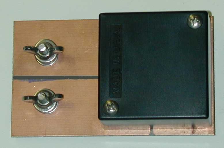
For a Reversible Beverage, I use the following:
Multiple Antennas at One Feedpoint
Never bring multiple antennas to one feedpoint, especially when they share
one common ground. I’ve noticed a definite deterioration in pattern with
multiple feedpoints arranged with only ten feet of spacing, even when they had
separate ground systems. One set of Beverages installed with 5-10 foot of
feedpoint separation has noticeably poorer patterns than other identical length
antennas with wide separation at the feedpoint.
Multiple antennas actually may be the only case where a sloped feeder can
make a difference, the slope will actually move the effective feedpoints further
apart. The best idea, however, is to separate the feedpoints by several times
the antenna height.
Termination Value
Having precise termination values isn’t necessary, but get as close as you
reasonably can. There are some impedance measurement suggestions circulating
that absolutely do not work. One is to just use a tuner to match the terminated
(or unterminated) antenna, and work backwards with loads to measure tuner
impedance ratio after matching. This won’t tell you a thing about proper
termination, unless you repeat the measurements on dozens of frequencies spread
over a wide range!
There are three fast, simple ways to test for proper termination:
With an Antenna SWR Analyzer
- Connect the antenna analyzer at the Beverage feedpoint through a good
matching transformer
- Sweep the analyzer frequency from 1.8 to 7 MHz (or over a ~4:1 frequency
range near the frequency intended for antenna) while watching SWR
- Adjust termination for minimum SWR variation (not
minimum SWR, minimum SWR variation!)
When installation (including grounds) and termination is proper, SWR
VALUE will remain nearly the same regardless of frequency
With an Antenna Impedance Meter
- Measure the feedpoint impedance (right at the feedpoint) of a roughly
terminated antenna at the frequencies of highest and lowest
resistive impedance. You can do this through a known good transformer by
correcting impedance for use of the transformer
- Multiply the lowest measured impedance by the highest, and then find the
square root of that number. This will be the correct termination
impedance of the antenna
With a Clamp-on RF Current Meter
(This does not work well with voltage, because of measurement method error
problems)
- Apply a small amount of power from a transmitter, do not exceed antenna
system component ratings!
- Measure current at the termination, and several points up to a distance of
at least 1/2 wl from the termination
- Adjust termination resistance so current shows a smooth current decline as
you move the meter towards the termination
Note:
In about 500-800 feet of distance, power loss in a Beverage is
around 3dB. This corresponds to a 1/3 reduction in current. If you
attempt to adjust for equal currents (or voltages) over any distance,
the antenna will be MIS-terminated!
Termination Components
Identifying a Composition Resistor
We commonly assume any brown phenolic resistor is a carbon composition
resistor, but that isn’t true. Most of the smooth brown-colored phenolic cased
resistors manufactured after 1960-1970 have actually been carbon film resistors.
There are only a limited number of manufacturers supplying carbon composition
resistors. One is Allen-Bradley. They are expensive special-order parts, and the
buyer must specify composition types.
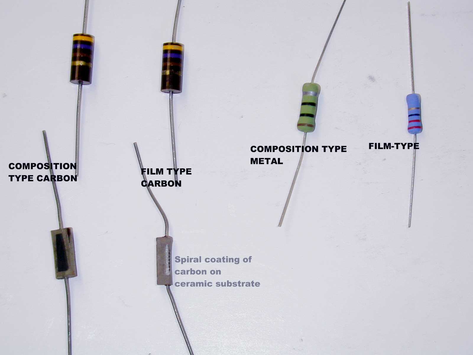
As we see from the photo, it is impossible to identify a composition
resistor by external appearance.
The only sure way to identify a resistor, short of ordering it from a
reputable source, is through a destructive test. We can, for example, apply a
large momentary overload and look for a resistance change. A resistance change
indicates a film-type element. We could also cut the resistor open, and look for
a non-conductive core. A non-conductive core indicates the resistor is a film
style component.
Why Composition Types?
We need composition resistors in any application where the resistor is
subjected to very-large very-short overloads, or where the system demands a
nearly pure resistance at a very high frequency (F>100MHz).
Obviously, in the case of a Beverage at a few MHz or lower, we could get away
with using many styles of wire-wound resistors or spiral-film resistors. A small
amount of inductance would not be a major problem, and virtually ALL carbon or
metal film resistors (constructed with resistance elements deposited or cut in a
spiral on an insulated core) would not have excessive inductance. The thing we
can not tolerate is the sensitivity of non-surge rated components to damage from
lightning storms, even distant storms.
The life of a carbon or metal film resistor, when used as an antenna
termination, is relatively short in most locations. Just a few coulombs of
energy, when applied in a few milliseconds, will cause a carbon or metal film
resistor to change value. Worse yet, the resistor will not be altered in
appearance. (Carbon also has a strong tendency to change value with heat. Even
modest operating temperatures, over a period of time, will cause a carbon
resistor to change value. Metal resistors are more stable.)
Unless you want to make a full-time career out of testing your antennas and
replacing resistors, use a energy absorbing composition type resistor!
I install a small lightning gap of about 1/8th inch across my antenna’s ends,
both at the feedpoint and the termination. This helps immensely with very close
strikes. I use either Ohmite OY-series metal compositions or A-B carbon
composition resistors. You can buy metal composition resistors at
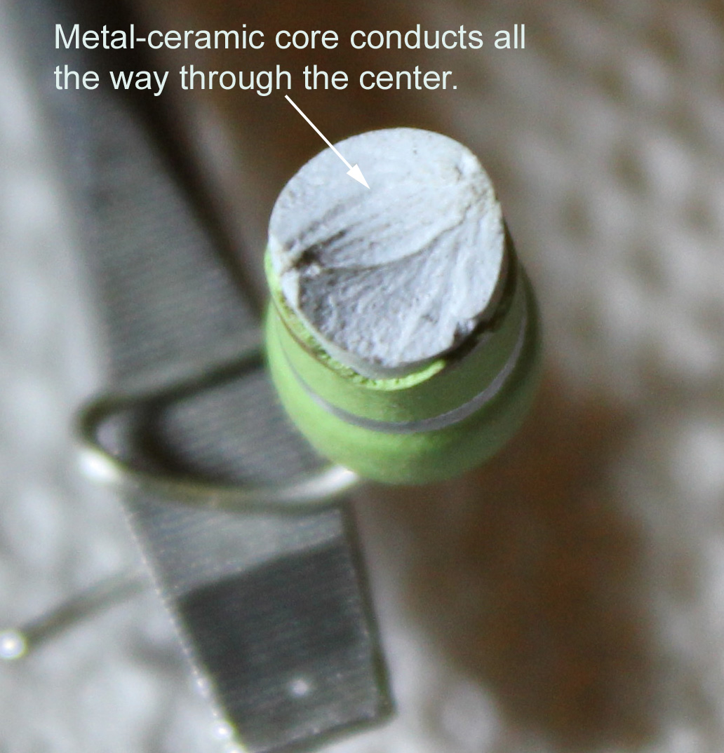
DX Engineering. A metal-ceramic composition resistor has a
metalized ceramic core. This makes it much more stable than carbon, and it
handles lightning surges much better than any other resistor type of similar
size.
Ground Systems
The ground system mainly provides an RF and lightning ground. Having a very
low ground-resistance is not especially important, unless an Autotransformer or
Un-un is used! Autotransformers and Un-un’s don’t isolate the feed line for common-mode.
The antenna needs a stable ground,
not necessarily a low-resistance ground.
In my tests over the years, a 3/4-inch copper pipe driven five feet or deeper
into the soil typically measures between 50-150 ohms of RF resistance on
160-meters. (DC or low frequency AC measurements will NEVER give the correct
earth resistance for RF, and they certainly can not tell us ground
conductivity.) Unless you have exceptionally poor soil, going deeper than five
feet will not reduce RF resistance on frequencies above 1.8 MHz. Skin effect
limits the depth of RF current in the soil, so the extra rod depth does nothing.
Lower resistance values (about 55 ohms) were obtained in a wet marshy area of NW
Ohio, with a very rich black acidic sandy loam soil. The higher resistance were
obtained in rocky clay soil typical of the Atlanta, Georgia area.
A word of caution. There are some very poor measurement methods for
determining soil conductivity and RF connection resistances, one of the most
popular using light bulbs. At 2 MHz, it is virtually impossible to find 10-30
ohm ground rod resistances. This is true even in saltwater, because of skin
depth. Any data claiming low ground rod resistances at high frequencies, or soil
conductivities (outside of salt marshes) over 30-40 ms/m, are likely based on flawed
measurement methods.
My present location has rolling pastures and wet clay soils, providing under
100-ohms of RF resistance at 1.8MHz with a five-foot rod. Deeper rod depth adds
virtually nothing, because of skin depth.
The general guideline I follow is to use at least two five-foot copper rods
(I use 3/4″ copper spaced 5 feet apart). If I can not get full depth, or if
the soil is particularly poor, I add a few 30-60 foot buried radials. The idea
is to obtain a reasonably stable ground, so termination does not change.
CLICK
TO LOOK AT ACTUAL MEASURED GROUND TERMINATION RESISTANCES!!!
If you are unsure if you Beverage’s ground is adequate, measure the impedance
of the beverage with an antenna analyzer with your operating ground systems.
Note the reading. Add two temporary radials 1/4 wl long suspended above earth at
right angles to the Beverage, and re-measure the impedance. (It is OK to have
them there at right angles to the antenna and not have them connected, and them
connect them while taking readings.)
You can measure the impedance on the low-Z side of a good transformer. Under
almost any condition, the wires would have 100 ohms or less impedance. If you
see a very noticeable change in impedance, you probably should consider
improving the ground system. Impedance changes of 15% (or larger) indicate a
potential ground stability problem, because the ground resistance would be
nearly 100 ohms. This test should be done when the ground is dry, or any time
you think you might be having a ground problem.
Always remember to keep the shield of the cable isolated from the Beverage
ground! Never use un-un or autotransformers.
Length
For length considerations, see the directivity factor
text. It has never been necessary to go beyond 1-1/2 or 2λ. By the time the
antenna is that long, current at the terminated end is so low, additional length
makes little difference. I limit my 160-meter antennas to ~800-feet long and use multiple antennas
broadside when a sharper
pattern is required.
Under some conditions, directivity can actually decrease if a longwire-type array is made too long.
This is true with Rhombics and V-Beams, and it is also true with
Beverages.
Zigzagging Wire
While a nice clear straight wire looks great, it does more to make us feel
better than hear better! Minor ups and downs in height, or dips or valleys, will not
significantly impact performance.
Although it probably is a good idea to keep the wire as straight as possible,
it is the overall direction and length that is most important because each small
area contributes on a similar small portion to the overall directivity and
signal reception.
|