|
Electronic Dynamic Bias Systems
Cathode Bias
Operation
Over the years I
noticed people being overly fussy
about having a
certain value
resistor for R1 in
the circuit below.
Allegedly resistor
R1 is needed to
“prevent the cathode
from soaring to B+
voltage” or
“establishing
cut-off bias”. Both
claims are generally
not true. Let’s look
at a working
example:

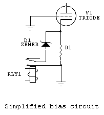
V1=3CX1200A7 (used
for measurement
data in this
example)
R1 is cathode
bias resistor when
relay is open
D1 is normal
zener diode
This is a
simplified bias
circuit, but it does
electrically
represent the
function of this
system.

|
R1 |
Bias |
R1 Pd |
Ip Amperes |
|
infinite |
24 |
0 |
0 |
|
100,000 |
21.3 |
0.0045369 |
0.000213 |
|
50,000 |
21 |
0.00882 |
0.00042 |
|
25,000 |
20.75 |
0.0172225 |
0.00083 |
|
10,000 |
19 |
0.0361 |
0.0019 |
|
5,000 |
17.9 |
0.064082 |
0.00358 |
|
2,200 |
18.018 |
0.14756742 |
0.00819 |
|
|
|
|
|
|
3CX1200A7 |
3650 volts anode |
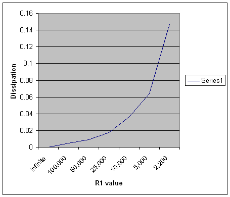
Table to the left
is dissipation in
watts for various
values of R1
resistance. Note
dissipation
increases as
resistance decreases
over this range. At
some point R1
dissipation will
peak and start to
decline as
resistance goes
below that value,
but this would be
with grossly
excessive standby
current.
Over a normal
range of R1 values,
dissipation is
insignificant.

|
R1 |
Bias |
R1 Pd |
Ip Amperes |
|
infinite |
24 |
0 |
0 |
|
100,000 |
21.3 |
0.0045369 |
0.000213 |
|
50,000 |
21 |
0.00882 |
0.00042 |
|
25,000 |
20.75 |
0.0172225 |
0.00083 |
|
10,000 |
19 |
0.0361 |
0.0019 |
|
5,000 |
17.9 |
0.064082 |
0.00358 |
|
2,200 |
18.018 |
0.14756742 |
0.00819 |
|
|
|
|
|
|
3CX1200A7 |
3650 volts anode |
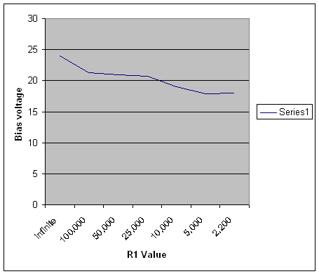
Table to the left
indicates measured
cathode voltage with
various values of R1
resistance. Note
that a completely
open circuit only
produces ~24 volts
cathode bias on the
3cx1200A7 tube! A
typical 3-500Z
produces about 30-35
volts cathode bias
with no resistor.
Note there is
very little change
in bias voltage over
the range of 2000
ohms to infinity!
The cathode is an
almost perfect
constant voltage source at
low currents.
Grounded Grid
Amps
|