|
Related page:
Fault protection
Please
note the
similarities in
power amplifier
protection and the
Kenwood radio!
A recent poster
on e-Ham suggests a
resistor in the
cathode of a TS830
functions as a fuse.
Here is the
circuit of that PA
section:
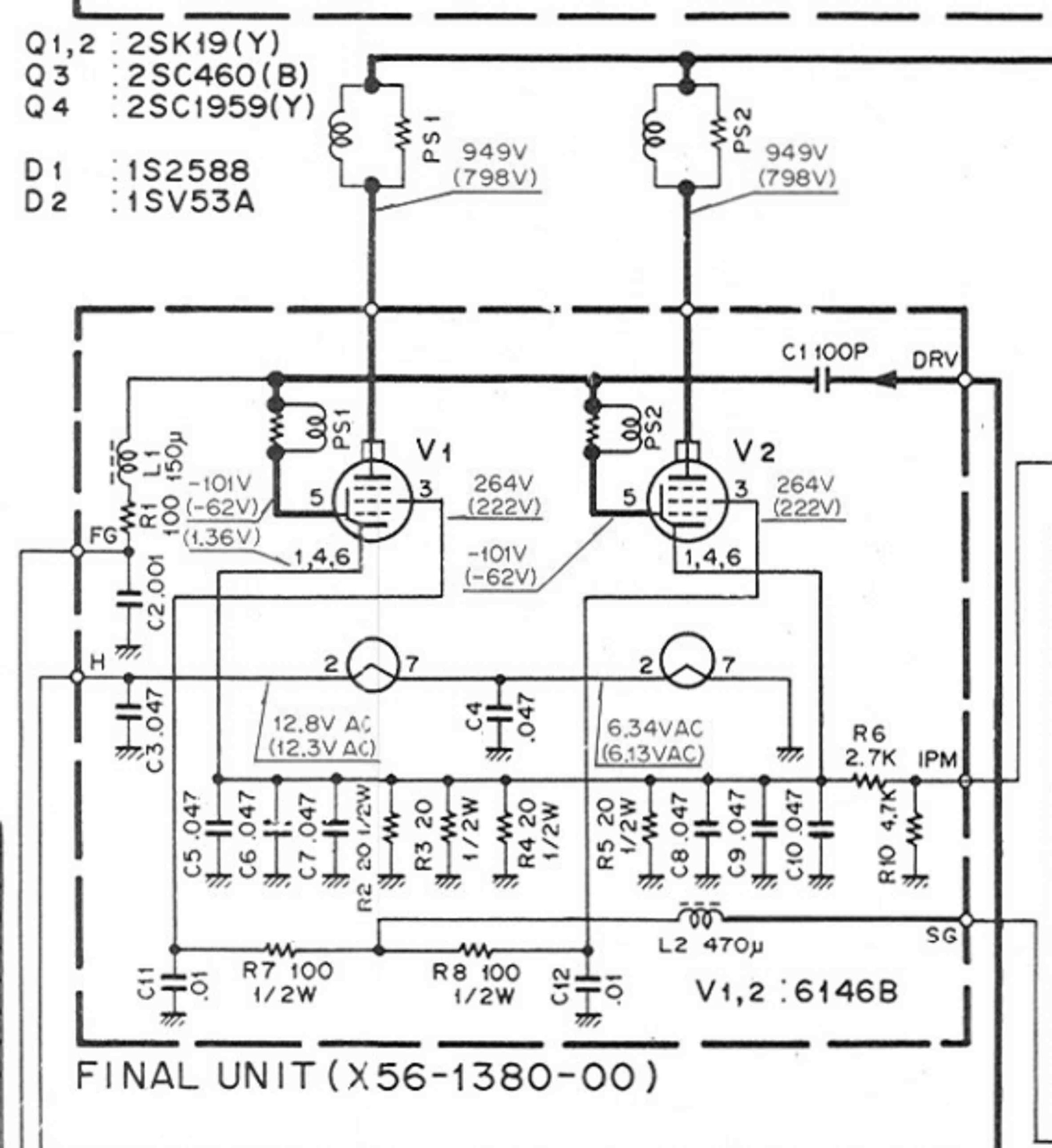
R2,3,4 and 5 are
the resistors in
question. Notice R6
and R10. They are
meter multiplier
resistors to
properly scale the
meter. The cathode
resistance in
question is
comprised of four
20-ohm 1/2 watt
resistors (R2-5) in
parallel, resulting
in 5-ohms at 2
watts. The typical
failure time of a
small carbon
resistor is anywhere
from a few hours to
infinity at fairly
large overloads. See
this reference:
and this report:
Examination of
data from commercial
manufacturers of
carbon and metal
resistors show the
resistors typically
withstand overloads
of 6 to 9 times the
steady state voltage
rating during
overloads for
several seconds
without significant
resistance change.
My tests have
shown carbon
resistors can
typically stand
several minutes to
several days at
dissipation
overloads of 500%.
It generally takes
an overload of
several thousand
percent to open the
resistor in a few
seconds, and ten’s
of thousands of
percent overload to
open instantaneously
or catastrophically.
Here is what
K4DPK found in his
experiments:
I paralleled
four 22 ohm 1/2
watt carbon film
resistors and
placed that
network in
series with a DC
supply and an
ammeter.
I ran 700 ma
through the 5.5
ohm network for
five minutes
continuously.
At the end of
that period, the
resistor network
measured 5.4
ohms, with no
signs of visible
damage.
K4DPK’s test was
only 2.7 watts
dissipation so it is
no surprise the
resistors did not
fail, but notice the
resistance decreased
after the overload.
This is the normal
cycle of carbon
because carbon is a
semi-conductor. The
resistance decreases
after long term
exposure to elevated
temperatures.
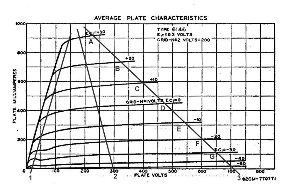
Now let’s look at
the 6146
characteristic
curves and see what
sort of resistor
dissipation we get
compared to stresses
inside the tube:
First let’s setup
some very strange
load lines that
represent gross
mistuning. Let’s
try maximum
current overloads at
minimum voltage
(line 1), medium
voltage (line 2),
and maximum voltage
(line 3).
Rated
maximum ICAS anode
dissipation is 25 to
35 watts depending
on tube type:
6146
AF Power
Amplifier &
Modulator – Class
AB1 (ICAS)
Plate Voltage
……………………………
750 V
Grid No. 2 Voltage
……………………….
250 V
Plate Input
……………………………..
85 W
Plate Dissipation
………………………..
25 W
Grid No. 2
Dissipation
……………………
3 W
Plate Current
……………………………
135 mA
Grid No. 1 Circuit
Resistance
Fixed Bias
…………………………….
100K Ω
Bulb Temperature (At
Hottest Point)
……….. 220 °C
6146B
AF Power
Amplifier &
Modulator – Class
AB1 (ICAS)
Plate Voltage
……………………………
750 V
Grid No. 2 Voltage
……………………….
250 V
Plate Input
……………………………..
120 W
Plate Dissipation
………………………..
35 W
Grid No. 2
Dissipation
……………………
3 W
Plate Current
……………………………
220 mA
Grid No. 1 Circuit
Resistance
Fixed Bias
…………………………….
100K Ω
Bulb Temperature (At
Hottest Point)
……….. 260 °C
On the above
loadlines, anything
over the following
values is excessive
dissipation in each
tube:
Loadline 1, curve
D, zero volts G1
Loadline 2, curve
G, -30 volts G1
Loadline 3,
unlabelled -40V G1
curve
The resistor
limit at full
rating, not at
failure, is 0.315
amperes per tube.
This is several
times the
steady-state plate
current for rated
dissipation. At that
point the anode and
power supply would
be really cooking!
That would be 630 mA
at several hundred
volts, or 400+ watts
from the supply.
Now let’s look at
the screen:
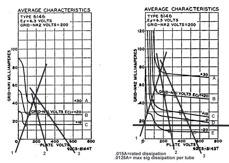
The thick
horizontal black
line is the screen
dissipation limit.
The thin-wire screen
has very low thermal
mass, making it very
sensitive to short
overloads. It is a
very rapid failure
element. All points
that produce
excessive cathode
resistor current and
dissipation, as well
as many of the
points that do not
produce excessive
cathode resistor
dissipation, result
in excessive screen
dissipation. As a
matter of fact some
points that just
barely reach the
resistors ratings
result in well over
five times rated
screen dissipation.
Would you call
the resistors fuses
or protection, when
the tube anode
and/or screen has to
exceed the rated
dissipation long
before the resistor?
The resistors are
really just a victim
of old age, a
momentary short in
the tube, or a
thermal runaway that
has damaged a tube
element. They are
almost certainly a
casualty of
tube failure, where
the tube breaks down
from internal
overload like a
red-hot screen grid
or anode that
outgases and causes
the tube to flash
over internally.
Additional
Discussion
Let’s look again
at the TS-830
circuit. From a
fault protection
standpoint, we would
NEVER want the
cathode resistors to
open. We would never
want them to be
“fuses”.
If the cathode is
allowed to rise to
even a fraction of
the B+ voltage there
is a very good risk
of damaging the
meter in the radio.
If the cathode is
allowed to rise to
B+ voltage there is
a large risk the
control grids and
screen grids can be
back-fed DC voltage
from the HV supply.
This would dump
several hundred
volts back into the
control grid
components causing
unnecessary damage.
If I had a rig
with metering like
this I would add
three series
connected rectifier
diodes, cathode or
“band end” facing
towards ground, from
the cathode of
either tube to
ground. This would
limit resistor
voltage to 2.1 volts
or so and protect
the meter. It
would also protect
the control and
screen grids from HV
discharge.
Where would a
fuse go? Let’s look
at the supply.
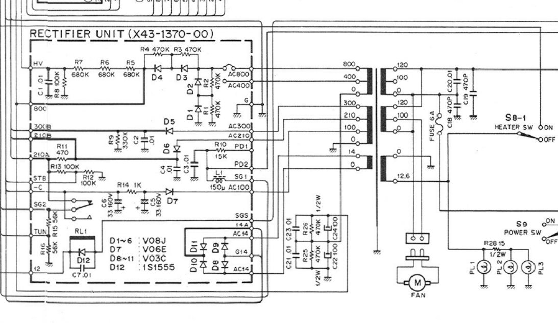
We would want a
glitch resistance or
sacrificial resistor
on the 800 volt lead
AFTER
electrolytics C22
and C24 tie into the
HV buss and before
the RF plate choke
of the PA stage.
I would use two
4.7-ohm to 10-ohm
energy absorbing
resistors in series,
like an
OY series Ohmite
resistor.
A pair of 4.7-ohm
OX or OY resistors
would limit fault
current to much less
than 66 amps, while
a pair of
ten-ohm resistors in
series would limit
fault current to
much less than 40
amperes. Think about
what I am saying
here in terms of
fault limiting. The
original system had
5 ohms of resistance
in the wrong place.
It would limit fault
current to less than
160 amperes.
Assuming the
original resistors
did anything at all
(I’m sure they a
would be more
harmful than helpful
in a fault), we
could now have four
times the fault
protection. This
sounds like an awful
amount of current,
but most components
could actually stand
that until a fuse
opened. For about
ten dollars we could
greatly increase
fault protection and
protect the
expensive panel
meter in the radio.
Glitch
resistors always
belong near the
energy source, not
in a grid, ground
return, or cathode
lead!
|