|
Counterpoise Definition
“Counterpoise” has been used by radio amateurs since the very
beginning of our hobby. When operators couldn’t
get a good earth ground, perhaps because they were on the second floor of a
house, the common suggestion was to “use a counterpoise wire”. A grid of conductors parallel to a dipole, laid on earth or suspended above
earth, is often referred to as a counterpoise. After all, the word “radial”
hardly fits a group of parallel wires with no real connection to the antenna’s
feed terminal. Counterpoise, in popular Ham radio conversation, has always
described a conductor or group of conductors serving as an RF ground.
Counterpoise definitions can be found in
dictionaries. Here is the definition of “counterpoise” appearing in the Communications Standard
Dictionary:
A
counterpoise is a conductor or system of conductors used
an earth or ground substitute in antenna systems. When we look at how
the word has been commonly used, we see general use and dictionary
definition agrees.
Model and Measurement Anomalies
Average gain can be a useful tool in EZNEC, as can maximum or peak gain. This
is how it is displayed:
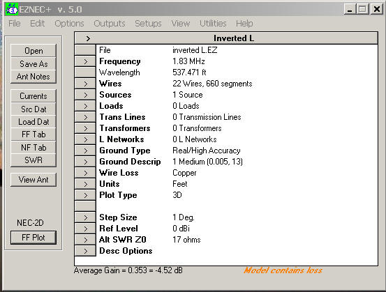
In this case, using a 3D plot, we see Average
Gain appear at the very bottom.
Average gain is .353, which translates to 35.3% radiation efficiency.
Also displayed is -4.52 dB, which is the total power loss of the entire
system.
Average gain is also an indicator of improper modeling if average gain exceeds 1.00, or is
unreasonably high.
Peak gain or maximum gain is another common performance indicator. It is
displayed in the pattern plot:
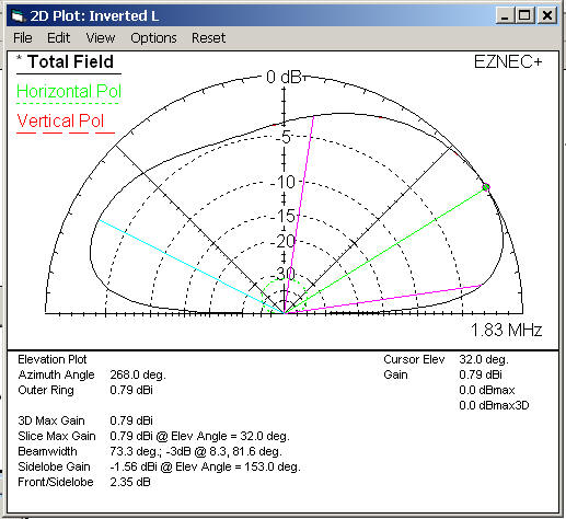
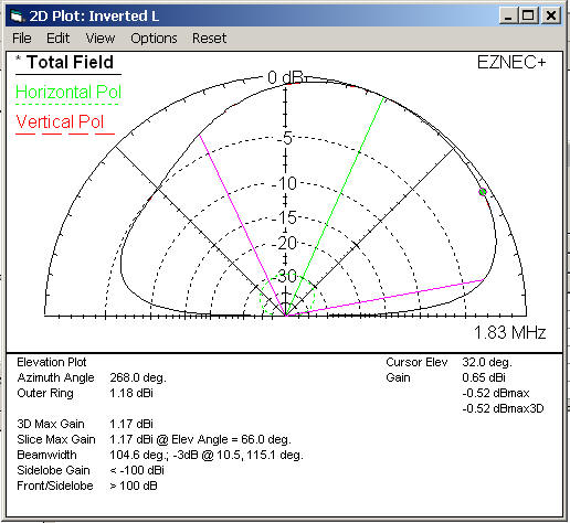
In this case we have a 3D maximum gain of .79 dBi at 32 degrees elevation
The counterpoise is made much smaller, and this appears to have slightly
better efficiency and average gain, but it is misleading.
By looking at pattern we see significant reduction in the left area of
pattern, and less gain at the lower, former maximum gain, angle. This is still a
useful comparison for peak radiation at long distances.
Remember patterns are plotted at a very large distance over flat
earth. This makes groundwave look like zero, and makes an already abused
parameter, take off angle (TOA), even less useful.
In a real vertical antenna less than ~3/4 wave tall, field does NOT
reach zero near the antenna at low angles.
|
An Inverted L, or any antenna with susceptibility to horizontal polarization, can give misleading ground efficiency results with compact or non-symmetrical counterpoises.
A full counterpoise below the flattop suppresses horizontally polarized
radiation. By removing or reducing ground reflection below the horizontal
antenna section, the low radiation angle vertically polarized Inverted L antenna
is moved toward “low dipole mode”. If we look at peak or average gain when
changing to a counterpoise or ground system that no longer suppresses horizontal
radiation, we can see what appear to be improvements. These peak
gain or efficiency improvements come from increased
horizontal radiation component, rather than improved vertically polarized field strength.
After modeling many systems, I’ve concluded the best antenna for comparing
ground systems is a top loaded vertical (for very short radiators), T vertical,
or full-size λ/4 vertical for taller
radiators. This keeps high angle “dipole mode” out of maximum gain or efficiency reports, especially when
doing earth-height efficiency sensitivity reports or evaluations. Otherwise,
if we use an antenna susceptible to horizontally polarized radiation, we must
compare absolute gain at low angles in all important directions.
feed lines and matching systems should be included in all models. It is
possible to “build” antennas that work very well in models, but rarely function
like the model in real life. Some well-known authors, including one who
pioneered early amateur modeling programs, have “invented” antennas that never
achieve predicted results because they never included feed lines, or tested for
sensitivity to feed line or matching system balance, or feed line or matching
system loss. This applies across the board to all antenna models, both receiving
and transmitting.
Those around me who do the most work and spend the most money, and have the
poorest results, mostly willy-nilly change to a better system without thinking
through changes, let alone documenting field strength changes. Every time one local amateur
changes antennas, the new antenna is always “killer”. He has gone from so many
“killer” to even more “killer” antennas, yet skimmer shows him the same
level as any other reasonable station from around here.
Another common, but low value, comparison method is contest results,
or DXCC totals. Scores trend
upward over time as people improve things. This is true for both skill,
increased activity, and
improved equipment. There are multiple causes at both ends
influencing results, including noise level, activity, equipment, human factors,
propagation, how enthusiastic we are, and even luck or fortune. We tend to
operate more when we “feel good” about something new, and operating more always
improves results.
Finally, false claims
and junk science universally depend on test errors, operator “feelings”, or
signal reports to support radial departures from good methods and science. It is not all that difficult to install reliable reference antennas with proper
construction and make A-B comparisons. The burden falls upon inventors of exceptional claims to provide
reasonable comparisons with systems known to work to some standard, not on
others to disprove them.
I can’t imagine changing antennas here without any idea if the previous
antenna was installed properly, or how the new antenna compared. I fell into
this trap several times before in my life, and it slows my personal progress. I
certainly have learned my lesson over the years. If I want to know something, I
directly measure, or measure as directly as possible, what I want
to know.
Counterpoise LF, HF, and MF Applications
Radials
Radial or buried screen systems, in direct soil contact, are generally
preferred in permanent installations. On lower frequencies, buried systems work just as well as
elevated systems. They also have much wider useable frequency range than
counterpoise systems. The broad frequency response of buried or ground-contact
systems not only helps cover wide radio frequency ranges, buried or ground
contact systems also offer significant lightning and electrical safety
advantages over ground-isolated systems. Buried or earth contact systems offer
grounding from dc to very high frequencies.
There is a popular myth among Hams and technical writers that USA Standard Broadcast systems require 120
radials. From that myth, people assume a “perfect radial ground system” requires 120
radials, each 1/4 wavelength long. This leads some to write articles or offer
advice stating peak efficiency requires 120 radials. The FCC actually says nothing of
the sort. 120 radials is not, and never was, considered a
minimum radial count for a “perfect ground” system.
If at least 90 radials
λ/4 are used, the FCC does not require
complex ground system efficiency proofs.
Ninety radials is the threshold to avoid spending money proving the
ground system works, even 90 radials is not a minimum requirement. Stations are free to use
fewer radials, and often do use fewer radials, provided they prove adequate antenna system
efficiency.
Exact FCC text is:
(4) At the present development of
the art, it is considered that where a vertical radiator is
employed with its base on the ground, the ground system should
consist of buried radial wires at least one-fourth wave length
long. There should be as many of these radials evenly spaced as
practicable and in no event less than 90. (120 radials of 0.35
to 0.4 of a wave length in length and spaced 3° is considered an
excellent ground system and in case of high base voltage, a base
screen of suitable dimensions should be employed.)
(5) In case
it is contended that the required antenna efficiency can be
obtained with an antenna of height or ground system less than
the minimum specified, a complete field strength survey must be
supplied to the Commission showing that the field strength at a
mile without absorption fulfills the minimum requirements. (See
§73.186.) This field survey must be made by a qualified engineer
using equipment of acceptable accuracy.
|
|
We see the FCC never said 120 radials make a perfect system, or even that 120
radials are the minimum requirement. The FCC said 90 radials will prevent having
to prove efficiency, and 120 radials
.35-.4 wavelengths, plus a base area screen if voltage is high, is considered
“excellent ground system” effort.
Reinvention of the FCC section above is commonly used to exaggerate
differences between conventional and
elevated systems. The typical exaggeration is something to the effect
of, “four elevated radials are equivalent to 120-radials on the ground”.
Such statements are very misleading. They imply or reinforce myths that 120
ground radials are required for a “perfect” ground. 120-radials were never established as a minimal
“perfect ground”. 120 radials are not even an “FCC mandated ground”.
Still, practical radial systems can be large. Without question, earth-contact
radial systems require more
wire than proper elevated systems for the same single-band RF performance. Note
this generalization is for a single band system, and also does not consider safety or
lightning mitigation. At my location a 7 MHz 1/4λ
vertical reaches the flat portion of efficiency improvement with
approximately 20-25 buried radials. That is still a
great deal of wire (~600 feet), although nowhere near the exaggerated 120-radial
requirement implies (3,600 feet). At my location, 12-15 buried radials (about
400 feet of wire) equals four elevated resonant radials (about 120 feet of wire)
when .05
wavelengths high on 40 meters. Wire savings is very close to 4:1, rather than
the falsely implied 30:1.
Field strength of my 160-meter 1/4λ
verticals, at my present location, stopped improving with around thirty-five ~1/4λ
long ground-contact radials.
Under almost all conditions 40-50
straight radials, each about .2λ long,
mitigates nearly all “ground” connection loss. Improvements going to 100 radials, or using longer radials,
are
less than 1dB. Less than 1dB change is almost always unnoticeable in terms of
performance on skywave paths. For all practical purposes, we can consider 30
radials 100-feet long a nearly perfect 160-meter ground. I do have 100 buried
radials 200 feet long on my 200-foot tower, but mostly for safety and to
function as a counterpoise or reflective screen for other antennas in that
field. I realize those radials are overkill for vertical efficiency.
I’ve also found base impedance a terrible way
to judge efficiency. I’ve had systems with 60-ohm base impedances produce the same
efficiency as systems with 36-ohm base impedances. Anyone making field strength
and impedance measurements on a variety of systems will quickly learn field
strength and impedance change are not locked in step. If we want to know field
strength change, we must measure field strength.
Counterpoise Systems
Counterpoise systems are substitutes for large RF earth-based ground systems.
Counterpoises, when properly implemented, can be very effective. Counterpoises
can also be a source of frustration, providing poor lightning and safety grounds, encouraging local
RFI (radio frequency interference), and sometimes creating receiver noise ingress
problems. Other than bandwidth and lightning/safety grounding, properly
installed counterpoise and radial systems will work about the same. Good
performance is more about not doing something wrong in either system than any particular system
being special or magical.
If something is wrong with an initial system, any change can be an
improvement.
We sometimes cannot freely choose our ground or counterpoise systems. Marconi antennas or end-fed antenna systems located far from earth require
counterpoises. Such systems are sometimes described as “groundplanes” or
“elevated radials”, although by definition they are also counterpoises. Another
application better satisfied by counterpoises occurs with limited physical space, or where
terrain or obstructions prohibit an adequate buried ground system of 20-30
reasonable-length radials.
While we should do the best we can, even compromise systems are better than
no system at all.
Cautions using Counterpoises
Counterpoises and sparse radial systems, such as four-radial groundplane
antennas, operate with considerable potential between the counterpoise and
“ground”. “Earthing” the counterpoise is generally a bad idea. Earthing occurs from counterpoise wires in very close
proximity, or direct contact, with earth. Wired counterpoise to earth paths have
a similar effect, often significantly reducing counterpoise efficiency. This includes accidental
wired paths to
earth through
feed lines.
A second detrimental effect comes from creating unnecessarily concentrated
electric induction (energy
storage) and/or magnetic induction fields around the counterpoise system.
Very short counterpoises, in terms of operating wavelength, cause very high
voltages to appear between the counterpoise and surroundings, including lossy
soil. Similarly, a single thin conductor has a very high surge impedance,
because capacitance distributed along conductor length is small compared to
series inductance. The high surge impedance increases electric field intensity
by concentrating the electric field. Making matters worse, without end-loading, a short conductor
concentrates current at the counterpoise feedpoint end, concentrating the
current and magnetic field.
Concentrating any field in a smaller cross sectional area of lossy media
increases loss. Reduced field concentration is why large area (in terms
of wavelength) radial systems have less loss than small systems, and why a big
thick carbon rod with large end-plate contacts that spread fields has less loss
than the same carbon rod with point contacts concentrating fields.
Unfortunately, space limitations and local obstructions often restrict
counterpoise or radial system size. When restrictions force a small system, we
can maximize available performance. There
are three ways to reduce earth losses near a counterpoise:
*The counterpoise can be made larger, with multiple cross wires. This
allows fields to spread, rather than concentrate in lossy earth
*The counterpoise can be elevated some height above from earth. This also
allows fields to spread, rather than concentrate in lossy earth
*All earth paths, including the feed line,
must be isolated or
insulated from
the counterpoise. This prevents conducted currents from directly entering
lossy soil
We sometimes hear radials or counterpoises need only be as long as the
vertical is high. Truth is opposite this myth. Shorter
verticals generally require larger and better grounds for peak efficiency.
The sole exception to 20-30 radials “being enough” occurs more often when an
efficiently designed and properly constructed vertical antenna is very short in
terms of wavelength!
Counterpoises and Local Fields
It would be nice if we could cancel local
reactive fields. Cancelling fields, or
making small spatial antennas seem large, has been a common thread running
through magical antenna systems. The E-H antenna, Super-C antenna, CFA (crossed
field antenna), Isotron antenna, and other antennas claim to have special
properties making them work like larger antennas. The common threads woven through these designs
are special shapes, phase, reduced induction fields, or increased conductor
thickness somehow mitigates
losses associated with reduced size systems.
While there are ways to minimize
deleterious interactions, most theories are founded in junk science. For example, proponents of small magnetic loops
often claim
lack of strong electric fields makes the loop less subject to local losses and
noise. They never
researched enough to see about λ/8
from the
small magnetic loop, the electric field dominates! Nether the small electric
dipole, or the small magnetic loop, maintains the same field dominance with
distance.
There
are dozens of ways to make small antennas or grounds that “work”, with none being
magical. Rest assured, if we cancel or
eliminate any field, we no longer have an antenna or counterpoise.
The real trick is to avoid design or installation errors.
also see Verticals and Baluns page,
and longwire page
If a radial system or counterpoise system has to be small, isolate the
counterpoise from earth paths. Decouple feed line shields. This can be worth
several dB.
The feed line shield is a commonly overlooked path for common mode currents.
The feed line can provide a path connecting earth resistance across the voltage
between counterpoise and ground. There should always be a shield RF isolation
device, a proper current balun or shield isolator will work. With a balun,
balanced terminals connect to the counterpoise and antenna, just as with a
dipole. While use of the term “current balun” may seem strange, but the
counterpoise system is not perfectly balanced or perfectly unbalanced. The
current balun does the same job it does in a dipole, ensuring the counterpoise
and antenna terminal share equal and opposite currents. This isolates the
feed line shield from the antenna feed terminals.
Failing to isolate the counterpoise from earth, which includes properly
elevating and insulating the counterpoise, can result in several dB loss on
transmitting, as well as bringing unwanted RF into the shack. While insulation
is better than a bare wire lying directly on earth, wide air spacing is by far
best.
feed lines are often left out of models. This can allow creation of systems
that don’t work as well as expected in the real world. By inserting a wire
representing the coaxial cable shield path, we can see the effects of
counterpoise to earth voltage in a model.
One way to observe maximum counterpoise-to-earth voltage in a model is to
insert a source set to zero current, or a load with very high impedance, in a
wire connected from earth to the counterpoise terminal at the feedpoint.
This is a small non-resonant T system with ~40-foot ground area
radius.
In this case, with non-resonant T counterpoises, voltage across a gap in wire 14 is
5300 volts RMS with 1500 watts applied to the antenna. This illustrates the
enormous electric field between counterpoise and earth using low-density
counterpoises with perfect ground-independent sources.
If we inserted a 1000 j500 common mode impedance balun in wire 14, balun dissipation
would be 277 watts. Common mode current on feed line shield will be 0.52 amperes.
A normal good-quality balun appears inadequate for isolating this small
non-resonant counterpoise system. Even 5000-ohms balun impedance is too low.
Isolation would require a high voltage
resonant choke, parallel-tuned to 160 meters.
Projections indicate this system
should be within 1-2 dB of sixty radials 100ft long, although optimum performance
might require counterpoise heights as much as 0.1 foot above earth per meter
wavelength. A 160-meter system might require 16 feet of counterpoise height, and
that will directly subtract from effective radiator height.
If we don’t isolate the ground path in this small non-resonant radial system, as much as 5 dB
loss can occur. If you have a small untuned counterpoise on or near earth, or
connected to earth through cable shields or ground rod, most of your transmitter
power can be wasted heating the earth. Much more power can be dissipated in earth losses than
radiating!
Without loading inductors in the four 8-foot high non-resonant radials, and
with a garden variety feed line choke, we have -3.2 dBi estimated peak radiation.
It can be even worse than this, but this might be considered typical.
This is the same radial system and antenna with a perfect ground isolation
feed line choke. Radials are NOT resonant. The only thing changed was the
feed line choke.
Resonance does not directly help the radials or antenna work better. Radials
greatly reduce the voltage from counterpoise common point to “earth”, and this
makes decoupling the feeder much easier.
Look at the plot below, where radials are made resonant. Field strength is
the same.
|
Out-of-resonance radials will also modify the resonant frequency of
the antenna system. Radial reactance is in series with the antenna feed.
Unless the feed line has considerable common mode currents on the shield
outside, adding reactance on the counterpoise side by mistuning the
counterpoise changes resonance and SWR just as mistuning the antenna
does. Mistuned radials will not only stress any feed line choke or cause
RFI, mistuned radials will also shift system resonance.
|
Adding 600-ohm reactance loading inductors in each radial wire at the feedpoint, and tuning for minimum counterpoise-to-earth feedpoint voltage, reduces 1500-watt counterpoise feedpoint voltage from
5300 volts to just 36 volts. Unfortunately, the
voltage null only holds over a small frequency range.
In this case, near radial resonant frequency, almost any balun or isolator will work. Running elevated radials
or counterpoises out of resonance is clearly a very bad idea, yet this is
exactly what many installations, including some manufactured systems, do.
Resonating the counterpoise, if it is a small counterpoise, significantly
reduces common mode problems.

Loading the radials at the T-junction improves field strength slightly, and
makes the antenna less sensitive to ground type below the antenna and
counterpoise height. This is a not a major increase with this particular example
of height and earth
type, although there are cases where improvement can be greater.
This is the same antenna with 40 radials 100-feet long.
Should people be amazed small ground systems work well when properly
installed? When we do a system properly, even a half-size system (40-foot radius in this
case) works OK.
The primary advantages of large systems are increased immunity to lightning,
reduced common mode on
feed lines, and much wider operating bandwidth. Large systems are less sensitive to ground
contact, more repeatable, less dangerous (lower voltages and field levels), and require less maintenance.
Resonate the Counterpoise
Resonating the counterpoise reduces counterpoise feedpoint-to-earth voltage.
This reduces common mode on the feed line, and relaxes current balun or choke
requirements.
One way to resonate the counterpoise is to measure counterpoise to earth
voltage at the counterpoise center, and adjust for minimum voltage.
A second way to tune the counterpoise is to disconnect it from the antenna,
and feed it like a low dipole. Adjust it for resonance.
Frequency Sensitivity
Multiband systems present a unique problem. The counterpoise or radial system
ideally must present a low common mode impedance across every operating band.
This is an extremely difficult goal if multiple bands are present.
Frequency sensitivity of a counterpoise can be modeled by placing the
counterpoise a few feet above a perfect ground, inserting a source in series
with a 50-ohm load in a short very-thick vertical wire, and attaching the
counterpoise to the top. By making a 50-ohm SWR sweep, a graphical
representation of low and high common mode impedances appears. The vertical wire
slightly skews frequency lower, but overall we get a good idea of frequency
sensitivity and problem bands.
Care must be exercised looking at the results. Reactance is not quite as much
problem as high resistance, because reactance can be “compensated out” with
changes in antenna tuning. High resistance will increase feed impedance
regardless of antenna length corrections or compensations, but will NOT
necessarily increase system loss. High SWR indicates bands or ranges where
feed line common mode or stress on feed line chokes will be problematic.
Here is a 1.8-30 MHz sweep of a 50-ft long single-wire counterpoise:
This plot shows a low common mode impedance at 4.8, 14.4, and 23.8 MHz. This
was roughly expected, based on length.
Making a four radial-wire counterpoise with 50-foot legs, we have:
We can see noticeable broadening of SWR nulls, and a slight downward
shift in frequency (mostly due to the vertical wire). Look at the following
systems:
Thirty 50ft radials:
Thirty 50ft elevated radials are bad only in the area of 10.8 and 21 MHz.
Sixty 50ft radials:
Interlaced 50 and 25 foot radials
We now have two more sweet spots, and have further narrowed bad areas:
We sometimes get surprising results. If we make the longer radials 60
feet, and the shorter radials 30 feet, we might assume we have fundamental 1/4λ
coverage of 80 and 40 meters, as well as
odd-harmonic coverage of the basic radial frequencies. We really have
this plot:
We have reasonable 80, 40, 15, 12, and 10 meters response, but no 20 meter
coverage, although the system is usable on most bands if we choke the feed line
and tune the antenna to correct reactance. The system is not terribly bad on 160
meters.
What happens if we make the same 60 and 30 foot radials close together, with
2 foot open-end spacing?
We now lose 15 meters. This is because the radials act like open stubs, and
detune 15 meters. We still have six nulls, but move and sharpen tuning and lose
some bands.
So how do we cover multiple bands? It looks pretty difficult without a large
screen or earth contact radials, unless we fiddle around until we move any
impedance bumps out of band.
Cover Largest Spatial Area Possible
More linear spatial area spreads counterpoise voltage (electric field) and
current (magnetic field).
Parallel Antenna’s Horizontal Element Areas
With antennas like T’s or L’s, orient a counterpoise parallel and directly
below horizontal antenna wires.
Various Configurations
T
Z or L
Y
X
Screen
Inductor Loaded
Folded or Stub Loaded
|