|
Background
Many antennas function because of common mode currents, rather than working
in spite of them. Two popular examples are CFA and EH antennas. Another recent example, appearing in Antennex’s compact antenna
articles, is a thick stub “vertical” with no counterpoise.
All of these antennas become
significantly poorer radiators if common-mode currents on feed lines are
eliminated. Why? Because the feed line is the actual radiator, NOT
the tiny thing they call the antenna.
Misunderstanding or misapplying Maxwell’s equations and the principles behind radiation, in combination with
missing some very key points of conventional circuit theory, causes problems. Some of us have
unwittingly attributed increased feedpoint resistance and/or
seemingly disproportionate amounts of radiation from very small structures to
new methods of radiating EM waves. Reviewing these antennas and the theoretical
or technical mistakes surrounding them will help us understand how
antennas and transmission lines work. With that knowledge, we can build better
antenna systems. The fastest and best way to learn is often to look in detail at
mistakes!
What They Claim
Articles and user reports of CFA, EH, and thick stub verticals
(without groundplanes) appearing in Antennex and other internet publications have one
common thread, the operational descriptions almost always include strong
indicators of problems with feed line common-mode current.
Authors commonly warn users to NEVER choke feed lines with baluns and to
“be sure the feed line is straight and in the clear”! Authors lay blame
for RF burns from feed lines or shack equipment on the antenna’s “high
radiation efficiency”, claiming these small magical antennas radiate so
efficiently they naturally excite the feed line and equipment more than full-size
antennas.
For example, the designer of the EH antenna claims the following:
“RF on the Coax
Due to the large radiation at the EH Antenna,
there will be some RF coupling to the coax. Whether this is a problem is
dependent on the radio you use. Some are subject to RF coupling into the audio
system, which causes severe distortion while transmitting. On some field day
setups with 100 watt transmitters we have had so much RF on the radio you can
get an RF burn. Below we have suggested ways to eliminate the RF coupling
problem.”
In the above statement, the designer actually acknowledges
current on the feed line shield and RF-voltage-on-chassis problems. The problem must be severe when a low-power
100-watt radio causes a burn. Like any good salesman, he turns a design
shortfall into a feature! According to the author, unwanted RF on the feed line
doesn’t come from a feedpoint or antenna design problem like it does on other
antennas, in this case the unwanted RF appears because the antenna works so well!
Here’s
what actually causes RF to appear on a coax shield and radio chassis. RF can only appear on the radio chassis
through two methods:
1.) The antenna, from poor feed line or feedpoint design, can couple to the radio chassis through external
wiring or cables attached to the radio.
2.) The radio chassis itself, being large in terms of the
wavelength, can actually become an antenna and receive energy from actual
desired “over the
air” signals.
(Many of us have these problems. Click on this
link to see one reason why.)
In this case, we can probably rule out reason two above. It is unlikely the chassis is a large portion of a wavelength
long on 20-meters and that the antenna field is suddenly so strong it is
“lighting up the house” with RF. After all, if power is radiating
effectively it will all be going out to distant stations and NOT cooking you or
the radio gear in your house! That only leaves reason one, poor feedpoint and
antenna design, as the cause of common-mode feed line or wiring currents
that excite
the coax shield and eventually the radio chassis, as described in method one.
Actually someone has measured this, and posted it to a web page!
http://www.home.earthlink.net/~calvinf15/_technical/
When the time-varying current from the transmitter flows in any
conductor, we will have charges accelerating in the cable. The
outside of a shield is no exception. A feed line’s shield will radiate proportionally by the
ampere-feet of the cable. just as any other conductor will. Of course the
antenna element will radiate also, but there is something else to consider.
A very small current flowing unopposed over a large
linear distance will
radiate quite a strong signal, because radiation resistance of a long antenna is
generally very high compared to very short antennas. You can find this
explained in the Radiation&Fields and
Radiation Resistance articles on this
site, and in engineering textbooks such as those written by Jasik, Kraus, and
Jordan-Balmain. From all of this, we know the shield radiates.
The inventor of the E-H antenna goes on to say:
“If you use RF beads, since the coax shield is not
a magnetic shield, the beads affect both the inner and outer conductors.
Therefore, most of the transmitter power will be converted to heat. Not good.”
Not a very knowledgeable statement at all, at least from
the standpoint of how shields work!
Time-varying fields can not pass through a shield
that is more than several skin depths thick. The inner part of the shield and
outer part are isolated by the skin effect, and nothing passes through. The ARRL
Handbook, Maxwell’s book “Reflections”, Reference Data for Radio
Engineers, and dozens of other amateur radio and engineering texts describe this
effect correctly. If we bring a time-varying electric field to zero in a system, the
time-varying magnetic field is also by definition zero. The shield DOES isolate
the center of the cable from time-varying magnetic fields on the outside of the
cable!
If that is true, why then does a shielded cable
passed through a current transformer used in a directional
coupler appear to pass RF magnetic fields? Why does the RF
magnetic field seem to “pass through” the shield of a shielded receiving loop
antenna? The answer is quite simple. There is a gap or intentional break in the
shield.
Current on the inside of the shield “spills over” the edge of
the shield where the shield is broken, and causes a current on the outside of
the shield. There is also a voltage across the gap at each end of the shield. We
have both our time-varying voltage and current, via a circuitous path to the
shield ends! Our Amateur texts explain that effect, as do all of the engineering
texts dealing with shields on transmission lines. If the gap is closed and the
shield’s ends are shorted together, making voltage across the shield gap zero, the
magnetic field no longer “seems to” penetrate the shield!
If a shield did not behave this way, we’d be in
serious trouble in the radio world. Without the shield stopping both magnetic
and electric time-varying fields, we could not shield our radios. We also could
not shield our microwave ovens, with non-magnetic materials!
If anyone thinks a ferrite core affects the
impedance inside a coaxial cable that does NOT have significant common mode
current, they only need to slip some beads over a cable on a working normal
“cold-for-RF” feed line. You will find absolutely no difference in system
performance when beads are added, proving Ted does not “have it right” in the text
above that appeared on the E-H antenna web site.
The author and inventor of the
E-H goes on to say:
“Use of a small choke made of several turns of the
coax is good. We find that a wire connected to the ground side of the coax at
the antenna and connected to either a ground rod or a wire laying on the ground
will eliminate RF problems – in most cases. For some radios we also need to add
a ground wire to the radio.”
Of course adding a ground wire might help! The ground wire becomes
the path for common-mode currents, or at least a portion of them. The additional
wire to ground becomes part of a long-wire antenna (made by the cable shield) that
actually does most of the
radiating!
“A preferred method is to run the coax to ground
then back to the radio. Near ground, connect the shield of the coax to a ground
rod or radial. Another method is to connect a wire from the radio to ground. If
the radio is very far from ground you will need to add a series resonant circuit
in the ground wire to effectively cancel the inductive reactance.”
It is understandable why this is a preferred
method! The outside of the coax shield can remain the primary antenna, saving us
the bother of installing the additional ground wire that becomes the antenna in
the previous suggestion!
“It may take one or more of the above to solve
your problem. Remember that if you have a good ground on the antenna, you have
also minimized problems with lightning.”
In the above text, we can see every solution carefully avoids
installing an effective choke balun on the feed line. A properly designed and
effective choke balun has no effect
on a coaxial feeder or system SWR, unless the feed line is radiating!
Let’s look at another E-H antenna experimenter and former proponent of the
E-H antennas test of a 160-meter E-H antenna. You can read the text directly
at:
http://www.qsl.net/iz7ath/web/02_brew/18_eh/english/pag11_eng.htm
Steve writes:
“With my short (and easy) tests I
deduce the EH lose about 10 dB versus my short 10 mt vertical with capacitive
hat in the top;
10 db is a big amount of power, but remember we are using 2 small cylinder of
37,5 cm on 160 mt band;
my vertical performed better than a 40 mt long sloper, so, may be, loss versus
full size dipole is not too much.”
Steve claims the E-H antenna looses about 10dB compared to a 1/4wl sloper,
which has an unpredictable efficiency. A typical sloper 1/4wl sloper is likely only around
50% efficient in the best situations, and more likely much worse!
The actual range can be from 10 to nearly 100% efficiency. Steve’s data repudiates
Ted’s claim and the CFA inventors claim that “crossed-field” antennas
provide high efficiency.
“There seems to be something good;
May be optimizing something we can have more gain (or, better, we can lose less
dB);
This antenna can be useful on the low band, expecially on 137 KHz (the EH
cylinder should be 6 mt high with a 2mt diameter).
On the web I’ve seen an other similar antenna (ISOTRON), wich seems caming (as
EH Antenna) from CFA antennas;
On the italian Radio Rivista (1995-1996) there were same informations about an
“Antenna Toroidale” wich in same way remember the EH: will be
interesting build and test one.”
Steve seems to be saying something we all agree with. A short
antenna will radiate, but not nearly as well as a full-size antenna.
“By the way, I think that my EH is
not for Dxing; it will be useful for that radioamateur who have no possibility
to install “long” antennas for low band, but want just to have local
QSO or few contest-contact.”
I agree! 10-20dB loss from a full size antenna would not make a
good DX antenna! Now here come the current-on-the-feed line problems:
“Other point: tuning;
I think it’s not as simple as others say; I’ve used an MFJ259B which tells me
all about the antenna, but the tuning was critical. On the other side
construction is easy;
I want suggest to you , when tuning, to connect the MFJ259B to the shack ground
(if there’s one). If not, EH will probably resonate higher (20-30 KHz).”
If grounding and ungrounding an antenna analyzer or any other
piece of equipment connected to a coaxial cable causes resonant frequency or SWR
of an antenna to change, the system has severe feed line radiation problems. See
my article on testing
baluns.
“Coaxial cable influence: inserting
more coax cable, the resonance seems to vary a little; I suppose that’s normal;
I don’t know for certain if the line radiates or not; I’ve added two iron-powder
coil forms back my TX and EH performance was unchanged. Then later I’ve added 2
big ferrite beads with a lot of turns on the roof (at the feed point of the EH)
and all has changed. My signal was 3 S point weaker than before and S.W.R was
very high.
I don’t know if that loss is due to the changed resonance in EH (as I said
before, outside the bandwidth performance goes down quickly).”
We see again that any attempt at reducing feed line radiation
results in an antenna that does not radiate very well. With the feed line choked,
Steve’s EH antenna dropped 3 S-units in addition to the original 10dB from his
sloper, or maybe 25dB or more!
There surely is a hidden message in all of the above contradictions!
How the E-H Antenna Really Works
There are many examples where designers intentionally use common-mode
currents. Examples are found in textbooks, such as the “Antenna Engineering
Handbook” by Jasik on and around page 22-6.
The antennas at the right, copied from Jasik’s textbook, outline the
derivation of a skirt collinear antenna from a simple feed line with the open end
terminated into a conductor.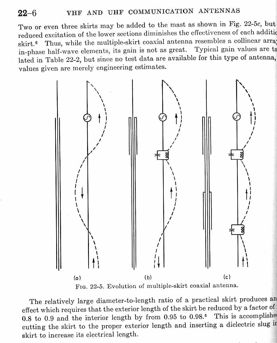
(It could be a ground rod or an antenna, like a Beverage or large loop, the
antenna does not have to be an “open circuit”.
Looking at (a), we find by hanging any conductor from the end of a coaxial
cable the shield is excited (on the outside) with common-mode current. The
electrical equivalent of the OUTSIDE of the shield is just as if a generator
located at the end of the shield was driving the outside of the shield as
longwire antenna. This goes along with Kirchoff’s Laws, that tell us the sum of
currents entering a point must equal the sum of currents leaving that point. For
any current to flow up into the antenna, and equal current must flow back down
over the outside of the shield.
With one ampere flowing up the center conductor into the “stinger”
at the coax’s end-point, the same level of current flows back over the
outside of the shield. (The shield’s inside and outside are isolated by the
skin-depth of the current at the operating frequency, an can be treated as two
independent conductors that are connected over the open edge of the shield.) We MUST
have this current simply because this is how coaxial cables work, the current on
the inside of the shield is ALWAYS equal and opposite to current in the
center conductor. There has to be some place for that shield current to flow, so
it makes the bend over the end of the cable and flows back down the outside.
This is also why, when we use a cable’s shield as a ground lead the center
conductor and inside of the shield do nothing to reduce resistance. Any current
that flows down the center conductor is cancelled by current flowing on the
inner wall of the shield, the result is no current at all flows down the center
conductor as long as the shield is several skin depths thick.
Many antennas intentionally and unintentionally use this principle, two
examples are shown in (b) and (c).
A recent Antennex Article on a “magical” ultra-compact antennas
claims an identical system, using a loaded fat cylinder, has an extremely high
radiation resistance and excellent performance because some magical
field-trickery increases the radiation resistance of a thick cylinder at
the antenna end. Certainly radiation resistance is somewhat high…but not for
the reason something magical or special is happening!
The small coil-loaded cylinder is actually only a fraction of the antenna
length, and being so short has a very small radiation resistance. The point
missed is the shield of the cable is very long, and is in series with that short
section. Since the shield is long, it also has a reasonably high impedance both
from radiation resistance and loss resistances. Shortening the length of the
end-stub results in an insignificant reduction in radiation resistance, because
the overall length of the radiating system is very long! We have a simple
off-center fed dipole, with one very long leg and one very short leg!
The main radiator is the outside of the feed line shield, not the tiny thing
being called an antenna!
Unless we make the coaxial shield an infinite length or pass it through what
amounts to an infinite groundplane with zero resistance, current continues on
down the cable shield. Looking at (c), we find even multiple sleeves appearing
as parallel tuned high-impedance circuits do not fully decouple the shield. Many
collinear antennas work on this principle, yet E-H antennas and others attribute
it to some form of electro-voodoo.
|