|
Tube cutoff bias
audio vs RF
Note: There are some
needless
modifications
suggested to the
EBS-1 system on the Internet. The
unnecessary modifications result from someone running
extensive tests, but unfortunately running baseband
audio frequencies directly into the EBS system. The EBS system is designed to
work from RF, not audio frequencies! It will not work properly when audio
frequency signals are applied directly to the input port.
If your
amplifier is working
properly and does
not have a defective
component in the EBS
system, it will work
fine without
modification. The
normal turn-on point
in an AL80B is about
0 dBm, or 1
milliwatt, on 160
meters. There are details explaining this below.
For all amplifiers, including
Ameritron, ETO, and ACOM, here are some general guidelines:
1.) If you hear voice chopping or noise gating from automatic bias,
you can be absolutely sure it is creating broadband CW clicks or
wideband “gating pops” on SSB
2.) If threshold is higher than -35 dB peak drive power, and does not
have a hang time, you can be sure the auto bias has the potential to
change envelope waveform.
3.) All amplifiers with auto-bias should be tested before operation,
and periodically after being placed in service, for low-level signal
operation on all bands. This test has to be made at radio frequencies,
an audio or function generator into the RF detector will NOT
work.
|
Testing the EBS System
Before modifications or servicing, EBS systems should be tested for proper
threshold voltage. The testing is very simple. Testing does not even require e
removing the amplifier cover.
You will need:
- A signal source covering the bands you operate. This signal source has
to adjust down to a few milliwatts. The signal source can be:
- a regular radio capable of a carrier adjusting smoothly down to zero
watts
- if your radio does not do this, you can use an audio generator
into the mic jack and generate a low level SSB signal by reducing
audio levels. Audio tone can be any frequency that passes the SSB
audio system. Exact frequency makes no difference
- a signal generator capable of up to +20 dBm output
- Some way to measure or know low signal power levels
- this can be a milliwatt power meter, a calibrated RF generator
output, or a good oscilloscope
- Connect a 50 ohm load to the amplifier
- Place the amplifier on the band being tested
- Place the amplifier in operate mode, and activate the TR relay by
grounding the relay line
- Observe the amplifier plate current with no RF drive. It should be near
zero mA
- Slowly increase RF drive from zero until the amplifier plate current
abruptly increases. Do not exceed 1/2 watt
- Measure the power level for plate current turn on. The ideal threshold
is always less than 100 mW, 20 dBm, or 3.14 volts peak with amplifiers
requiring 100 watts of maximum drive power
- Slowly decrease RF power level. Plate current should abruptly decrease
at some slightly lower level, ideally around 70% or less of turn on power
- Test all bands of interest
- If the plate current does not increase at levels less than 100mW, 20
dBm, or 3.14 volts peak, the EBS system has a threshold problem
Electronic Dynamic Bias System
EBS-1
or HF Amplifier auto-bias theory
The idea behind
automatic electronic bias is a
reduction of
quiescent current
and heat in high
power radio-frequency
amplifiers. The
basic idea is when
RF drops to a very
low level, large amounts of quiescent
current are not necessary. A proper
auto-bias reduces quiescent current under
low-level conditions, but never takes the plate current to zero or grid bias to
or beyond cutoff.
This reduces heat
and can save a significant
amount of wasted energy.
In order to
function properly a
few conditions have
to be met:
- The bias system must never go deep class C, and must
never
force cutoff bias to needlessly high levels.
Resting bias
must hover at or around tube
cut-off voltage.
- The bias
system must
respond rapidly, even with
very little radio
frequency input
voltage. Linear operating bias must be switched on faster than syllabic or CW envelope
rise. There must be adequate
hang or turn-off delay at the falling edge of exciter RF output.
This requires a
fast attack system
with long hang time.
- The bias
system has to
switch on with
drive levels far
below levels where
high PA current is
required. This is to minimize turn-on clipping.
- The bias
voltage, when
switched on by higher RF levels,
has to be stable. This will minimize intermodulation products.
Automatic or
dynamic electronic bias
systems work extremely well, so long as conditions above are met. On the other
hand, many auto bias systems create needless problems. The general rule is if
you can hear truncating of background noise or leading edges, the system is
causing some level of wideband spurious. Designs can improve
when we look at, and correct, past mistakes.
Poor Bias Systems
The old Alpha 77 EBS system has major problems. The Alpha 77 design forces
the 8877 tubes hard
into cutoff. +20
volts cathode bias would
have been adequate,
but the ETO system
forces bias well
above that level.
Under no-signal
conditions the
excessive bias
pushes the tube(s)
deep into class C,
instead of properly being at
the edge of class B. With grossly excessive cutoff bias voltage, the Alpha 77
has to pull the bias
down from an
unnecessarily high
cut-off voltage (near 100 volts) to a
few volts.
When the bias starts out much higher than necessary, any electronic dynamic bias
requires significantly more time to pull out of cutoff and become linear. Worse
yet, very low level signals are either not passed, or are passed through a
class-C system. This causes chopping and
distortion (RF signal gating) at the start of
each RF syllable. This insures very low
level signals are
not amplified, at
least for a short
period of time. Excessive time delay in reaching linear operating
truncates and squares the envelope’s rising edge, and causes extremely wide
bandwidth leading edge clicks on SSB and wide leading edge keyclicks on CW.
A properly designed electronic or automatic
amplifier bias system
would have the tube(s)
hang at very
slight conduction
current. A very small level of quiescent current keeps the tube(s) into AB class at all times,
even though it would be very deep AB class (at the very edge of class B). With
minimal quiescent
current, resting dissipation is virtually the same as full cutoff. While
maintaining deep class AB,
nearly all RF idling heat would be generated by the tube filament.
It’s a good idea to
have a self-bias
resistance shunting
the electronic switch in any EBS system.
A shunt self-bias resistance
could be designed to hold the
PA system slightly in
conduction with a
minimal amount of
quiescent current. A
2-5k ohm resistance
should be good enough for most high-mu triodes.
You might want to
read about
cathode bias at this
link.
Some Chinese tubes, in particular 811 and 572 tubes, require
some forced bias. I believe this is because grid end construction allows
electron leakage to the antenna, causing them to act like remote cutoff bias
tubes. This is abnormal behavior. It is not found in older European and USA 711
and 572 tubes, or in all batches of Chinese tubes.
Typical Electronic
Bias Circuit
Operation
In the circuit
below, C2 serves
only to couple the
1.8-30 MHz
transmitter energy
into a standard
diode voltage
doubler. In order to
properly double, the system needs a dc
path from the R6
side of C2 to
ground. R1 limits
diode and Q1 base
current. C5 is an RF
smoothing filter. R2 loads the
base of switch Q1.
Q1 has a 1.4 volt
threshold, although
a standard bipolar
would switch lower.
Q2 is a switch that
turns on when the
base goes below
resting bias
voltage. It follows
bias voltage down
until D3 eventually
clamps at around 9
volts.
D3 will set the
“on” bias voltage.
R8 limits diode
current in tube
arcs. D4 clamps the
open circuit to a
reasonable voltage,
and can normally be
omitted if triodes
or tubes are
actually used in
place of R99 (see
what happens in the
cathode at the
cathode bias link up
above).
C6 adds a little
hang time. R5 limits
discharge current of
C6 while C6
recharges to an
“off” state through
R4. C3 is just an RF
and transient
bypass. There is a
great deal of
additional external
capacitance not
shown.
There actually is
no part of this
circuit with “audio”
unless Q1 is not
fully on. When Q1 is
fully on, the
collector is simply
grounded. It is only
when RF drive goes
below two volts or
so that Q1 passes
any “audio”.
A 2 volt level
typically
corresponds to a
power level of about
40 milliwatts into
50 ohms. At times background
blower or room noise
will have that
level. (40 mW is 34
dB below 100 watts
PEP.)
The Signal Detected
There seems to be
a
little
confusion
about what comes out
of the ANTENNA
connector in an HF
radio. The exact
words used were:
I sent this
private email
hoping to start
a constructive
dialog. . .
Hi OM,
Your model is
all messed up!
The analysis is
meaningless
because you
applied audio
frequencies to
the input
instead of radio
frequencies. The
lowest possible
frequency on the
input is 1.8
MHz, not 10 Hz
or even 3,000
Hz. Why would
anyone model an
RF detector with
audio
frequencies
applied?
73,
Tom W8JI
This is his
publicly posted response:
“His statements
took me back a
bit. One should
know that a
“modulation”
envelope is what
SSB produces
(not a
‘carrier’), so
in the limit
(using math
jargon), a 50hz
‘tone’
modulating the
SSB Tx at some
RF frequency is
one example.
Since low
frequencies
(50hz) are
easily produced
in the newer
radios (FT-2000,
FT-9000, etc)
the problem
centers on the
inability of
most EBS ckts to
pass these low
frequencies @
low level b/c of
two (2) main
factors:
improper time
constant (too
short) and input
passband skew
(shifted toward
high
frequencies).”
|
The above
response to my e-mail highlights a misconception that I’ve seen several times
over the years. It
appears some think audio frequencies
appear at a transmitter’s
antenna connector.
Some apparently think audio baseband frequencies appear at a transceiver’s RF output connector, and
are
processed through the amplifier system and antenna as baseband audio. I’ve even, on rare
occasions, heard Hi-fi audio (ESSB) people describe how
a push-pull RF
amplifier has less
RF intermodulation or
splatter, which is
also just as silly! It’s easy to
understand this
confusion, and it’s
generally easy to
straighten out the misconception with
most
people.
How a SSB System Works
A SSB transmitter is really a frequency convertor. It ideally converts audio
to a similar bandwidth RF signal through various methods. If any
HF SSB transmitter
is modulated with a single tone,
such as a 50 Hz tone,
the transmitter
output actually
contains no 50 Hz
energy at all! Let’s look at why this happens.
Let’s consider a SSB transceiver tuned to 3.800 MHz . When the suppressed
“carrier” frequency is set at
3.800 MHz and we
apply a
steady 50 Hz tone to the balanced modulator or digital equivalent of the
balanced modulator,
the RF output
frequency is actually a pure
radio frequency sine wave at
3,799,950 Hz. The radio is actually a complex frequency convertor, converting
audio signals up to a selected radio frequency. The spectrum is either inverted
on LSB with higher pitched tones becoming lower RF frequencies, or non-inverted
on USB with higher tones producing higher RF frequencies.
This
“conversion process” is why a 50 Hz
tone passes right through
antenna tuners,
coax, and eventually radiates
from a 3.8 MHz
dipole! This is why we do not need 50 Hz coupling capacitors in RF systems, even
when the baseband audio signal is just a few Hertz. If the 50 Hz signal, or some
other low signal frequency, actually appeared and required transmission, our
130-foot long 80-meter dipoles would be far too short!
At the
receiver the “TONE” goes
through a series of
bandpass filters,
none of which need
to respond to 50 Hz!
Why? Because the
tone is converted to
radio frequencies by
the transmitter!
Obviously, there is no need for the EBS or any electronic bias system to respond
to 50 Hz at the RF detector. 50 Hz is clearly not present at the
amplifier RF input or at the cathode of the tube, or anywhere in the system
beyond the balanced modulator and prior to combining with a local carrier
oscillator!
In the receiver
the RF tone is
converted to new
frequencies,
eventually reaching
a final “mixer”, or
product detector,
that reinserts a
local carrier
oscillator. This creates
a new “difference
frequency” on the
proper sideband, and
passes the newly
generated difference
frequency out to the
audio stages. It is
at this point, and
this point only, the
50 Hz energy finally
reappears. As a
matter of fact if
you mistune the
receiver slightly
we never get the
original 50 Hz in
this example, we
get some other
entirely different audio frequency.
If we look at
that same 50 Hz
modulated 75-meter
SSB single tone on a
spectrum analyzer we
would see this
spectrum:
The single tone RF
output, regardless
of audio tone input
frequency, is a single
narrow RF spike that
actually is a steady
unmodulated RF carrier!
Years ago Collins and other
companies
generated CW this
way, by using a 1000
Hz tone injected into the
audio of a SSB
exciter or
transceiver. The
output frequency of
any SSB transmitter is
indeed a single RF
frequency when
modulated by a tone.
This radio frequency
tone, or plurality of
radio frequency
tones (for speech or
two-tone tests) far
above the baseband
audio frequency
range, is actually
what the electronic
bias system detects.
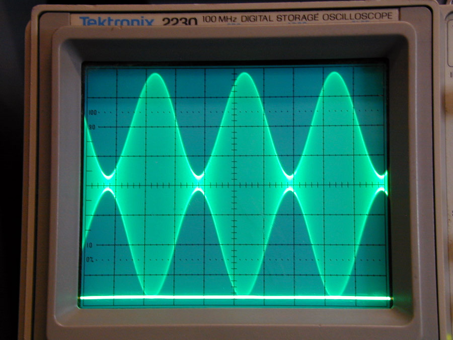
At any instant of
time during
modulation of a SSB
transmitter, watching with an oscilloscope, we see
the waveform similar to the waveform below on
the transmitter’s RF
output port:
Note there is no
energy in the
modulation at 50
Hz!! It is all on 75
meters (in this
example) as it should
be.
How would we
model this single-tone SSB system in
spice? Like this….
Note voltage
source V1 is a 8-volt peak-to-peak RF
(2.828 volts RMS)
generator. It feeds
a 50 ohm load. The
power is .16 watts,
or 160 milliwatts.
For a two-tone
source, typical of
speech, we would
need to simulate the
actual RF signal.
Say we had a tone of
50 Hz and 2500 Hz.
The 3.800 MHz LSB
transmitter would
now output two
frequencies,
3.799,950 MHz for the 50
Hz tone, and
3.797,500 MHz for the
2500 Hz LSB tone.
The resulting
drive waveform looks
amazing like a
two-tone test
instead of a
carrier, because it
is a two-tone
signal!
The waveforms and
circuit shows none
of the problems
caused by using the
incorrect simulation
of audio frequencies
to represent a radio
frequency signal.
When the bias
signal switches on,
which actually
occurs in about
.17 milliseconds on
the initial leading
edge, bias
stabilizes and sits
at about 9 volts.
This is
significantly faster
than the rise time
of a CW signal
(normally 5 ms) and
so causes very
little distortion to
the applied
waveform. Only the
very first cycle in
a series of cycles
is modified. This
model says the EBS-1
(very similar
circuit, not exact)
should “turn on” at
about 2 volts peak.
Let’s see what
happens below with a
“real one”.
EBS-1 Test
Enough of spice
models, let’s look
at how an EBS-1
really works.
.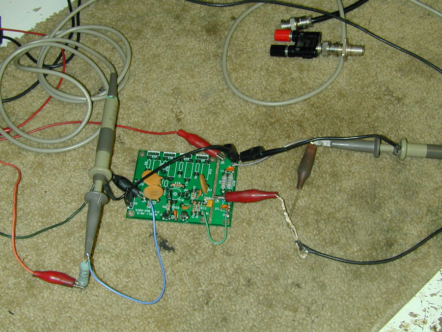
Source voltage is
a 35-volt power
supply.
Dropping resistor
is 150 ohms, 7
watts.
This is the audio
test where audio
frequencies were
applied.
For RF, the
coaxial line with
BNC connector is
attached. Audio
lines go into a low
power 3.8 MHz SSB
exciter.
Below: Threshold
of the EBS-1 is 10
volts peak-to-peak
at 50 Hz. There are
3 volts of 50 Hz
ripple on the bias
line! This would be
no good!
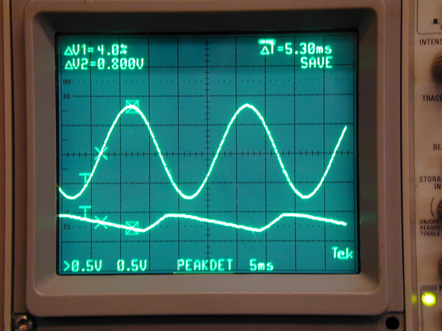
The scope has 10x
probes.
In this case with
audio
improperly applied
to the RF port of
the EBS system, we
see a saw-tooth
waveform with about
7 volts p-p ripple
in the bias line.
The applied audio
level is 5.8 volts
peak, or 11.6 volts
peak-to-peak, and
the EBS has not
turned fully on.
This is why the EBS,
with stock component
values, cannot be
connected to the
microphone or audio
lines of a
transceiver. It must
be connected to the
RF input of the
amplifier, and it
must be tested and
evaluated with the
RF signals it was
designed to operates
with.
The problem with
the test above is
every HF radio we
use does not apply
audio to the EBS-1
detector. The radio
applies RF!
Let’s apply 3.8
MHz RF from the same
50 Hz tone into an
“ESSB” single
sideband transmitter
audio line input and
see what happens.
This is with signal
level right below
threshold:
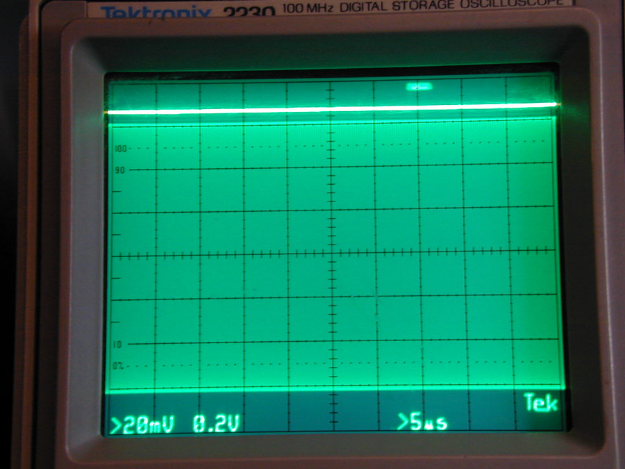
Scope has 10x
probes. Multiply
scale by ten.
Scope is now set at
20 mV/div for
RF trace with zero
at very lowest scope
graticule, and
.2V/div for RF trace
with zero at the
center graticule.
This makes bias
range 16 volts full
scale, and RF range
.8 volts full scale
both + and – the
zero center.
Bias is about 15
volts (upper bright
line) with .6 volts
peak RF, or 1.2 V
p-p RF
(.0036 watts into 50
ohms). This is bias
HIGH (PA biased just
beyond class B) at
5.5 dBm , or 3.6 mW of RF.
3.6 milliwatts is not much drive power, but turn on at such low levels is
required for click-free CW operation of auto-bias systems!
Next we increase
RF drive until bias
turns on:
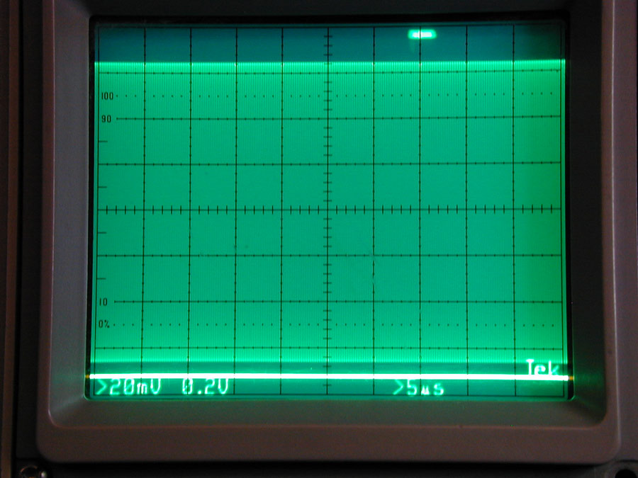
Now we are just
barely above .6
volts peak, probably
right around .64
volts. This is about
4.1 milliwatts into
50 ohms. At this
point the bias is
clamped low for full
anode current. With
just a .5 mW
change, the EBS-1
went from standby bias mode to
linear amplification
mode.
This is the bias
system voltage with
the RF envelope
below the turn-on
threshold. In this
case the transmitter
power would be .33
volts peak, or 1.08
milliwatts PEP into 50
ohms.
The scope is at
.1V/div, with 10x
probes.
Bias is at
35 volts.
This very slight
increase in drive to
1.30 mW PEP pulls the
bias solidly low,
and holds it there
through a two-tone
50 Hz and 2500 Hz
audio into the
transmitter.
This slight
apparent increase in
drive level is
actually caused by
most of the envelope
being below turn-on
threshold, not by an
actual increase in
required switch
level. There is a
fractional
millisecond time
delay for any
waveform, with a
constant maximum threshold
of about 5.0 mW at 50
ohms. The EBS
actually is not
trying to turn on
until the dotted
scope lines are
reached.
In the previous
trace where bias
stays high, there
just is not enough
envelope time
above level
threshold to
activate.
Frequency Response
The following shows
frequency response
of an unmodified
EBS-1 board.
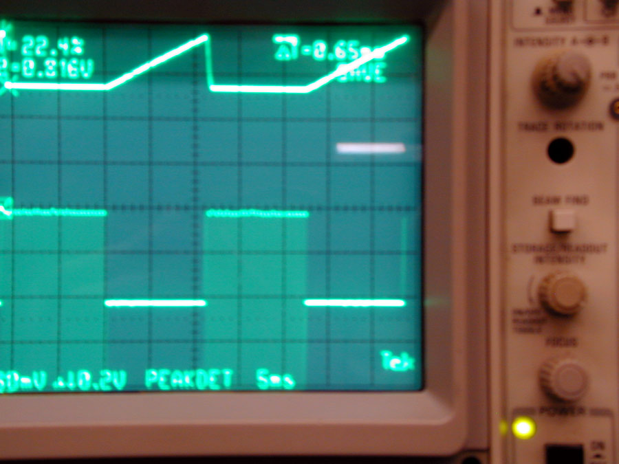
The total turn on
delay time from full
bias to full clamp
(minimum bias) is
0.65 ms with a 20
dBm (100 mW) pulsed 3.8 MHz
signal.
This means if we
drove an amplifier
with marginal signal
levels that were
above turn-on
threshold, the
actual bias delay
time to stable bias
would be 0.65 ms.
The actual
bias scale in the
photo is 1 volt per
division. Zero is
set at the white bar
at the left, just
above the third
graticule down from
the top. Low bias
voltage is about 1
volt @ 500 mA.
Highest bias voltage
reached with this 50
Hz square wave is
about 2 volts, still
well within the
linear region of any
amplifier tube.
Cut-off bias does
not fully recover
between 50 Hz
“pulses” in this
photo, so the
amplifier bias
remains almost as if
it was never
switched off.
All of this is important for click-free CW operation with auto bias.
Ramped Input
Threshold Response
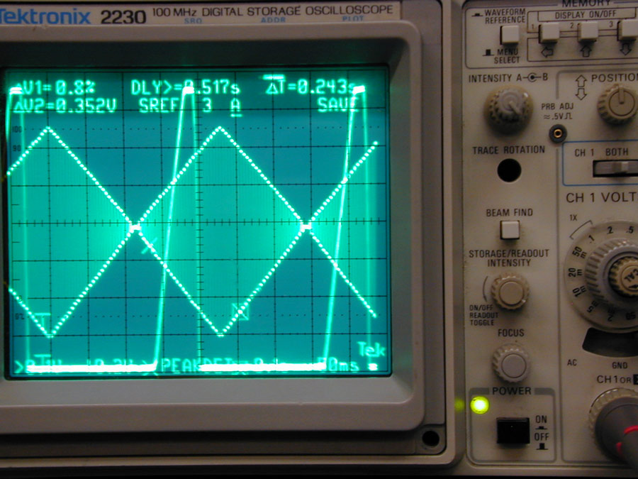
This test shows
the threshold under
a very slowly rising
modulation envelope
waveform. This is a
2 Hz modulation
envelope at 200 mW
PEP on 3.8 MHz..
Sweep is 100 mS
per division.
The EBS-1 goes
from full bias to
zero bias at about
5.0 mW.
It recovers to
full bias in about
2-1/4 divisions, or
1/4 second. This is
the on-bias “hang
time”.
The response is
.5 mS on delay, with
250 millisecond off delay
(hang) time. Turn-on
threshold is about
6.5 mW.
electronic bias
system amplifier
The EBS-1,
contrary to
incorrect spice
models on one
website, works just
fine. Any single
tone RF signal
over 5.0 mW (1.24V
peak-to-peak) into
50 ohms on 3.8 MHz
turns the EBS-1 on.
Even a pure 50 Hz
tone driving the
radio will activate the EBS at that time and level! Any
multi-tone signal
over 10.0 mW peak also
turns on and solidly
clamps the bias low.
Bias stays in transmit mode even
during modulation
minimums, where power
virtually reaches
zero. This is
because the EBS
system has fast
attack response with
a slight hang time.
Suggested Changes or
EBS
EBS-1Modifications
Early in EBS1
production, I made a
mistake. I derived
the EBS switching
voltage from the RF
Input port side of
the input
pi-network. This
caused a problem on
some bands on some
frequencies, most
notably on ten
meters. This is
because the input
network, with an
“open circuit load”
caused by the tube
being biased into
cutoff, loaded the
exciter drive down.
This raised the
switch on voltage to
several volts,
instead of the
desired 1-2 volts.
The cure for this
problem was to
relocate the EBS RF
sample point after
the input circuit,
on the tube side of
the input system.
Early production
amplifiers may have
the EBS RF sample
taken from the RF
input side of the
input network, and
this early system can cause
problems on some
bands with some
exciters.
After testing in
a few amplifiers,
I’ve recommended
Ameritron add a 2.2
K 2-watt metal film
resistor across the
switching
transistor. This is
to improve slower
speed CW signal
response through the
EBS system. This
keeps the tube very
slightly into
conduction so slower
CW speeds through
slow rise time
transmitters are
amplified without
leading edge
truncating and
sharpening of the
dot or dash
elements. It isn’t a
good idea to remove
the first .5 ms of
the leading edge of
every element. This
does not affect
sound on SSB, it
does not affect
cooling of the PA
tube.
For now, I’d
appreciate any
technical feedback
on this article to
my e-mail address. I
do not always
respond because of
time restraints and
the number of emails
I get, but I do read
everything sent from
other Hams.

|