|
Related Pages:
Filters
Optimum Filter and Stub Location
Optimum filter and stub location is dependent on source and load
characteristics. Optimum location is almost never independent of position along
the transmission line. Optimum filter or stub location is not always, at the
source or load, as many Handbooks and sources suggest.
Let’s look at how an amplifier’s pi-network and pi-L network behave
when followed by various loads. Looking at a 40 meter amplifier’s pi-network we
have:
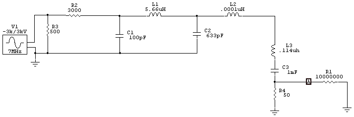
In this base case, we have a 50-ohm load. The series load reactances, L3 and
C3, are set to negligible reactance, or to desired values, before running the
model.
Fundamental load voltage is 200 volts, or 800 watts load power. 14 MHz
harmonic level is .5 volts, or 5 milliwatts. This is -52 dBc suppression. This
ASSUMES, incorrectly for most real systems, load impedance is 50 j0 across the
entire HF spectrum.
An antenna, a stub, or a filter will present different impedances at the output port
on different frequencies. We cannot use a dummy load, or a 50-ohm system like a
network analyzer or generator sweep system, to measure the real harmonic
attenuation. In a real system we would
have the following 14 MHz 50-ohm antenna 2nd harmonic levels with various
20-meter shunt impedances at the output port:
| Termination Shunt Impedance |
Harmonic voltage level volts |
Harmonic power level |
Harmonic Attenuation dBc |
| broadband load 50Ω j0 |
0.5 |
5 mW |
-52 |
| 2Ω +j0 |
.057 |
65 µW |
-70.9 |
| 2Ω +j10 |
.119 |
283 µW |
-64.5 |
| 2Ω +j20 |
.458 |
4 mW |
-52.8 |
| 2Ω -j10 |
.0362 |
26 µW |
-74.8 |
| 2Ω -j20 |
.0273 |
14.9 µW |
-77.3 |
Inductive reactances can decrease harmonic suppression, while capacitive
reactances at the harmonic frequency increase harmonic suppression.
Since harmonics are not perfectly terminated, except with a dummy load or
wideband antenna, we never have the wideband 50Ω
measured or predicted harmonic suppression. In nearly all systems the reactance sign and level varies
with distance from the amplifier tank to the filter, and it also varies with the
type of filter. This means where we place a stub or filter, including how the
antenna system behaves at the harmonic, determines stub or filter performance.
Anyone telling us a certain filter or stub offers “xx dB attenuation”, or
always should be at a certain spot in the system, is overstepping the limits of
accuracy.
Pi-L Network
By resetting C1, L1, C2, and L2 to different values, we now have a pi-L
network in our representation of an amplifier.
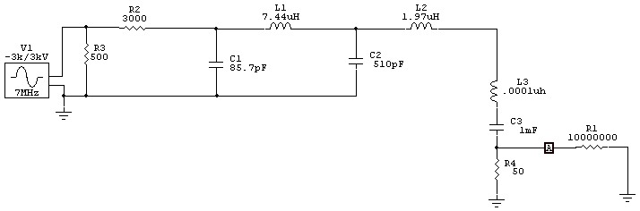
In this case, we have a higher-than-normal Q pi-L with 200Ω
center
impedance, feeding a 50-ohm load.
Series load reactances, L3 and
C3, are set to negligible reactance, or to desired values, before running the
model.
Fundamental load voltage is 200 volts, or 800 watts load power. 14 MHz
harmonic level is .19 volts, or .72 milliwatts. This is -60.4 dBc suppression.
This model
ASSUMES, incorrectly for most real systems, load impedance is 50Ω j0 across the
entire HF spectrum. This is the same assumption network analyzer and other sweep
measurements usually assume. It is more than ironic that people fiddle and fuss
to get stubs a certain length, when optimum length might not be close to optimum
length for results in a broadband 50Ω system or
model.
| Filter Shunt Impedance |
Harmonic voltage level volts |
50-ohm Harmonic power level |
Harmonic Attenuation dBc |
| no filter |
.19 |
720 µW |
-60.4 |
| 2 +j0 |
.0086 |
1.48 µW |
-87.3 |
| 2 +j10 |
.0069 |
.95 µW |
-89.2 |
| 2 +j20 |
.00664 |
.88 µW |
-89.6 |
| 2 -j10 |
.0074 |
1.1 µW |
-88.6 |
| 2 -j20 |
.0076 |
1.2 µW |
-88.4 |
| 2 -j80 |
.017 |
5.78 µW |
-81.4 |
We want to avoid capacitive reactance at the tank output on harmonics
with a pi-L, because it can reduce harmonic suppression.
These models do NOT represent worse case conditions for load impedance. They
are intended to demonstrate getting fussy or extreme about stub length is
probably a waste of time and energy, unless the stub or filter is actually
pruned and tuned for your specific system.
Sometimes things in life are so complex being overly fussy is nothing but a
waste of time.
Link to
|