|
The folded dipole is claimed to offer increased bandwidth, and to closely match 300-ohm line. This
is much like the double bazooka antenna, or coaxial dipole antenna. Inaccurate double bazooka and coaxial dipole claims have been debunked in numerous
forums and texts, including in QST and Reflections by Walter Maxwell.
While double bazooka or folded dipole antennas can offer significantly more
bandwidth than a thin wire dipole, it is important to understand why
certain antennas have more bandwidth. Let’s look at a folded dipole and see how it really behaves.
Folded Dipole Myths
Myth #1:
-The advantage of using a folded dipole is wide bandwidth.
False: On a single band, bandwidth is essentially no different than
just tying the legs in parallel, splitting it in the center, and feeding it
with coax. We will see this in the models below. A folded dipole, like any
dipole, is wider primarily from being made thicker. It does not get
significantly wider not from the stub effect or folding, and not from the
higher feed line impedance.
Myth #2
-When used on other bands, the higher natural impedance tends to swamp
the impedance from being non-resonant, which makes for easier matching.
False: The folded dipole is only useable with reasonable feed
efficiency on the fundamental and on odd harmonics. The folded dipole is much
worse than a regular ladder line fed dipole dipole for harmonic or
out-of-band
operation. On even harmonic bands, it appears as a nearly dead short. On odd
harmonic bands, the resonance shifts upwards, typically about 4-6 %. It is
not a good multiband antenna, and actually has excellent radiation
suppression of even harmonics.
-A twinlead folded dipole fed with twinlead will have an impedance around
300 ohms on the designed band. Variations in folded dipole SWR is less with changes in antenna
length or frequency are less than in a regular coax fed dipole.
False: SWR variations are essentially the same. A regular coaxial fed dipole varies from ~50 ohms
to ~70 ohms or so over normal height ranges. This means 50-ohm SWR can be as
high as ~1.5:1 with normal height variations
With a folded dipole, impedance varies between ~200 ohms to about 300 ohms. This
also means SWR can be as high as ~1.5:1 over normal height ranges!
Myth #4
-The folded dipole has the advantage of using balanced line feed, and
balanced line has low-loss at high SWR.
False: Loss has little to do with being balanced, except the lack of a shield
increases surge impedance. 7/8th inch
diameter heliax coax, for example, has less loss than 1 inch wide “window” or
“ladder” line. The real reason balanced lines can operate with reasonable SWR on
multiband doublets is the antenna impedance. A dipole’s impedance is about 4000
ohms or less on even harmonics, so SWR is only 10:1 on a typical 400-ohm
balanced line. If the feeder was a 50 ohm line, SWR would be 80:1!
On the fundamental and odd harmonics, the dipole impedance is about 50 to 100
ohms. That impedance is near perfect for coax, and the ladder line is still only
8:1 or less.
Bandwidth
Don’t be fooled by claims wide bandwidth means high loss, or that narrow
bandwidth indicates high efficiency. Bandwidth is related to system Q, but
system Q is not determined solely by resistive or heat losses. System Q is
really a function of stored energy to energy moved through the system. Energy
can be moved through the system and exit as wasteful heat, or it can exit as
useful work. An antenna 5 kHz wide can be far less than 1% efficient, while an
antenna 500 kHz wide can be almost 100% efficient. Without knowing where energy
is going, we should never assume bandwidth means anything other than bandwidth.
Most antennas store a majority of energy in an electric field, although small
“magnetic” loops have a lot of energy in a strong, very local, magnetic field.
The folded dipole is no exception to this generalization. The folded dipole, like almost any antenna, has an
electric field boundary at the wire to space transition. Current flowing into
the antenna “travels”
through space via displacement currents. The displacement currents are a function of
voltage and capacitance along the conductor to the outside world.
The electric field boundary is most intense at the open ends of the antenna,
and this gives rise to most of the antenna’s energy storage. As we spread this
boundary region out, reducing electric field concentration, stored energy
is reduced. Reducing stored energy reduces Q, and increases bandwidth. At the
same time, it might actually reduce loss.
When any antenna is made thicker, the energy storage boundary is more evenly
distributed. This is especially true near the open ends of an antenna, such as
the end of a dipole.
The folded dipole obtains virtually all of any bandwidth improvement by
virtue of being thicker, especially near the outer ends. We will see this
demonstrated below.
The fact the arms also form “stubs”, as with the coaxial dipole, has almost
no bearing on bandwidth. The folded dipole is wider bandwidth than thinner
dipoles, and narrower than thicker dipoles, when loss is constant. Any bandwidth
improvement mostly comes from being thicker, but some actually comes from
slightly increased loss.
Basic Wire Table of Folded Dipole Model
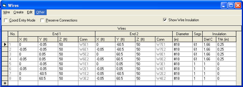
Feedpoint
I constructed a model that allows a relatively easy change from folded dipole
to dipole.
VSWR Curve of Folded Dipole with 300 Ohm feed line
2:1 VSWR at 3.65 and 3.9 MHz. 2:1 bandwidth using 300-ohm line is 250 KHz
VSWR Curve of Folded Dipole with 200 Ohm feed line
2:1 VSWR with 200 ohm line at 3.635 and 3.86 MHz. 2:1 VSWR bandwidth is 225
kHz
Fed as regular dipole, no other changes:
Feedpoint:
SWR Curve 50-ohm coaxial fed regular dipole made with same
size and materials
2:1 VSWR at 3.635 and 3.85 MHz, VSWR Bandwidth 215 kHz
SWR Curve 75-ohm coaxial fed regular dipole made with same
size and materials
2:1 VSWR at 3.64 and 3.89 MHz. 2:1 VSWR BW is 250 kHz
#14 (regular) insulated Wire Dipole
2:1 VSWR 3.63 – 3.8 MHz 2:1 VSWR BW = 170 kHz
Summary
| Type |
feed line |
Lowest SWR |
2:1 SWR BW |
| Folded |
300 |
1.4:1 |
250 kHz |
| Folded |
200 |
1.05:1 |
225 kHz |
| Regular same wire |
75 |
1.4:1 |
250 kHz |
| Regular same wire |
50 |
1.05:1 |
215 kHz |
| Regular single #14 wire |
50 |
1.25 |
170 kHz |
We can see there are negligible differences between folded dipole and regular
dipole systems unless we change the effective wire diameter!.
|