|
The magic “T” combiner
or splitter is a very useful device. It can provide equal
voltages, equal current, or equal power to matched or unmatched loads.
How it works depends
on the termination
resistance, R1 in
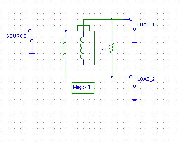
figure 1 below.
The magic-T is not
a magic bullet.
While the magic-T
isolates two sources
or loads from each
other, the source
port must be set at
half the resistance
of R1 to provide
this isolation. The
magic-T or any other
splitter or combiner
will not
eliminate the
effects of mutual
coupling in
antennas.
The basic element looks like this:

fig. 1
Remember the
source and load
ports are
interchangeable.
In other words this
device can be used
to split or combine
signals simply by
making sources loads
or loads sources. If
we fed signals into
load ports, the
source port would
contain the vector
sum of signals
applied to the load
ports in fig. 1
above.
The source
impedance is 1/2 of
the load impedances
when both load
impedances are
equal. With two 50
ohm loads (or 50 ohm
sources) at LOAD1
and 2, the source
port (this port
would be the load
port when combining)
would be 25 ohms.
For maximum
isolation between
the right hand ports
the optimum R1
resistance would be
100 ohms. It is
always twice the
resistance at the
left hand port
in fig 1.
If R1 is omitted,
the Magic T becomes
an equal current
source for the right
hand ports. If the
transformer is
shorted the voltages
would be equal on
all ports, and the
transformer would
have no purpose.
The single port
on the left is
usually fed into a
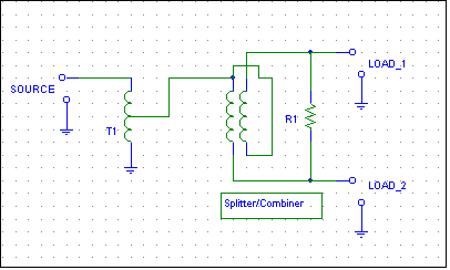
1:2 autotransformer
(1:1.414 turns
ratio) that steps
the impedance up.
This makes the
optimum impedance
equal on all three
ports.
Transmitting
Applications
Splitters and
combiners like this
are often used in
linear amplifiers to
combine multiple
power amplifiers.
The optimum winding
style and materials
is dependent on
impedance, power
levels, and
frequency range.
Higher power systems
at HF tend to use
physically larger
cores, and the
permeability is
reduced in order to
find cores with
lower loss tangents.
A typical 1500 watt
HF combiner might
use a two inch deep
core of 67 material,
while the step-up
autotransformer
might use 43 or 61
materials of similar
size.
The advantage of
using a combiner
like this is the
amplifier input or
output ports are
isolated from each
other. This reduces
intermodulation
caused by mixing in
the power
amplifiers, and
improves stability
by isolating
amplifier ports from
each other. It is
much safer than
simply paralleling
ports.
Receiving
Applications
For 0.1 to 30 MHz
low power receiving applications, a nearly ideal transformer is a twisted pair of small
(number 18 to 26 gauge) enameled wires with five to seven passes through a 73
material one-inch binocular core. The source impedance is parallel combination
of the two load impedances, and generally is stepped back up through a 5:7 turn
ratio (1:2 impedance ratio) transformer. R1 is twice the load impedance in
splitter/combiner applications. (I’ve seen some commercially produced systems
for amateur use that violate the design guidelines and offer terrible return
loss and isolation.)
Like all passive splitters and combiners, this device is less than ideal.
Isolation is maximum only when at least one port (sometimes two depending
on
application) are properly
terminated. In this
case isolation
between the two
right hand ports is
maximum when the
left hand port is
properly terminated.
As mentioned
earlier, this system does have an interesting characteristic.
It can force
equal currents into two different load impedances (or equal power by adjusting R1
to some value between zero and infinity). If R1 is open, each load is forced to
have equal currents regardless of load impedances. If R1 is shorted, the loads
always equal voltages
(T1 can be removed and the entire circuit configured as a T connector). Keep in
mind this rule is true ONLY at the port of the splitter. Transmission lines have
the effect of changing voltage and current relationships.
By forcing equal currents, a 1/2 wl transmission line can be used to feed a
directional array instead of the more typical odd-1/4 wl line. With a 2:1 load
resistance unbalance, I measured less than 0.1dB current error in such an
application.
With a perfect load or source, the splitter generally serves no useful
function at all. There are specific case where a splitter or combiner can be
beneficial, but these are mostly case where amplifiers or amplified antenna
systems are combined. As a general rule when the systems have bilateral
impedance characteristics (an antenna without an amplifier would be an example
of a system where source and return impedances are equal) a splitter or combiner
is not necessary, and the combiner really serves no useful function.
As a matter of practice I use splitters and combiners regardless of system
characteristics because they are not that expensive and they can, if the system
is not perfect, reduce problems or performance shortfalls caused by impedance
errors.
Virtually all splitters are based on the Magic T with a matching
transformer on the input. These splitters are certainly less than ideal, but they
are simple and many times (but not always) better than a direct parallel
connection.

T1 is a 7-turn transformer tapped at 5 turns (1.4:1 turns ratio, 2:1
impedance ratio) step-down transformer. 73 material binocular cores are
ideal for 100kHZ to 30MHz applications.
The magic T transformer is 5 to 10 turns of twisted pair wire through a 73
material binocular core. Configured as a center-tapped winding.
R1 is twice the expected load impedance. For 50- ohm systems use a 100 ohm
resistor.
Losses
Typical loss of the Magic T is 3dB per port. The only other significant loss,
when properly terminated, is a slight loss in T1. Normal loss of the entire
system to either output port is 3 to 3.5dB. When combining in-phase signals,
loss is only the loss in T1, there is no “combining loss”.
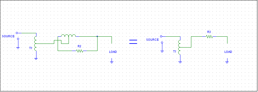
When the Magic T splitter or combiner is open-circuited on one port, the
electrical equivalent is:

In a properly designed magic-T, R2 is twice the value of any port. This
resistor is stepped down by the
impedance ratio of 4:1 in the center tapped winding (no part designator) when a load port is opened. In
a 50-ohm system, this effectively results in 25 ohms (R3) in series with
the load impedance of 50 ohms. The resulting impedance of 75 ohms is doubled
by T1 to 150 ohms. Assuming ideal components the input SWR, when the
output is open on one port, is 3:1.
Loss will be 1.25dB from mistermination of the source by the 3:1 VSWR
(assuming it is a 50 ohm source) with an additional loss of 1.7dB as power
divides between R3 and the output port. The theoretical open circuit loss
(including transformer losses) is about 3 dB, the same as if a load were
connected. The SWR, however, is NOT matched (1:1) like it is with a proper load
on all ports!
The Magic-T behaves in a similar manner if one output port is shorted,
with the exception R2 appears directly across the load. This is the equivalent
of a 100-ohm resistor shunting a 50-ohm load. This impedance (33.34 ohms) is
quartered by the center tapped winding of the Magic T to 8.3 ohms. T1 steps this
impedance up to 16.6 ohms. The result is once again a 3:1 VSWR.
This means signal level at port 1 theoretically does not change when port
2 is open or shorted, or any termination between an open or short. The impedance
(and SWR) DOES change, so mismatch loss and phase angles will vary a great
deal.
Like many systems, these losses are based on source and load impedances being
ideal. This is almost never the case, and the optimum value of R2 is often
significantly different from being twice the load resistance. Because of that,
our actual systems may show significantly more level change than the ideal theoretical
amount (theoretical is no change) when one port is incorrectly terminated.
Consider this device in a receiving antenna system. If the preamplifier system does
see the correct load impedance, the overall system will probably lose more gain
than we might expect. The gain loss will very likely come with the penalty of lower IM performance. This is
particularly true if the low-headroom amplifiers typical of amateur radio
“preamplifiers” are used.
Even with high dynamic push-pull CATV transistor amplifiers, I’ve often found
it necessary to optimize the splitting system. For example, my receiver
distribution system has 8 antenna inputs. Antennas are all independent in
directional control (multi-op), or can be linked to a common direction control
(normal use). The antenna input ports are amplified and then split to feed
multiple receivers, any of which can instantly switch to any splitter output.
My switching matrix looks like this:
| |
RX1 |
RX2 |
RX3 |
RX4 |
| Europe 3x Bev |
|
|
|
|
| Europe 2x Bev |
|
|
|
|
| Europe BSEF Vert |
|
|
|
|
| 8 circle of verticals |
|
|
|
|
| Front Beverages |
|
|
|
|
| Middle Beverages |
|
|
|
|
| Rear Beverages |
|
|
|
|
Distant low
dipole 2500 feet
away |
|
|
|
|
This is 32 combinations of receivers and antennas.
My stock my R4C’s
typically have ~20-ohm input impedances on 160-meters. My receiving system is
designed around 75-ohm cables and hardware. It is cheap, very q good quality,
and connectors are reliable and easy to install. If I connect a ~20 ohm R4C on one port
and a higher-impedance receiver (or worse yet an open-circuit) on the other
port, the result is t results in starving the already low-sensitivity R4C receivers for signal
(despite the use of a “splitter”) if they are used in conjunction with
higher sensitivity higher impedance receivers like FT1000’s. The solution is to
make every load (all the receivers) look like 75-ohms, readjust R1 to a new
value, or use emitter-follower “active splitters”.
I opted to make all of my receivers “look like” 75 ohms and
terminate unused ports, but your
choice may be different.
Amplifiers
Caution must be used in selecting amplifiers. Virtually all commercial
amplifiers I have tested have very limited dynamic range. They are fine for
amplifying high-loss antennas like Flags and EWE’s, but terrible when connected
to large Beverage systems. Adding an additional 6dB or more gain to the output
of a Beverage just to overcome splitting losses (plus problems associated with
uneven power division) almost always pushes these amplifiers “over the
top”. If you are going to use single-ended amplifiers with small low-power
devices, be prepared to use multiple amplifiers (one for each receiver) and
place them after the splitter system.
It is far better to buy or build one good amplifier, but it should be a very
high dynamic range device!
|


