|
Circularly Polarized Waves
Circular polarization is traditionally generated from an antenna system that
launches a V and H wave with phase lead or lag in the polarizations. This is
traditionally considered to be from a V and H antenna, because we are
conditioned to think in those terms for electric field polarization. The wave
actually does not have to come from two sources, as referenced to the earth at
90 degrees (vertical) or 180 degrees (parallel to earth or horizontal). Two
antennas, one at 45 and one at 35 degrees tilt, would work just as well. It , or
it could also be any other polarization angle 90 degrees apart, like 20 degrees
and 110 degrees.
If we stood at one point and looked into a circularly polarized wavefront, we
would see an electric field rotating as it moved toward us. The arriving wave
would be continually rotating with a rotational period of the reciprocal of the
frequency. A 1.830 MHz signal would be rotating in a 1/1,830,000 period for
360-degrees rotation. This is about 0.546448 µS
for a full 360-degree rotation!
A circularly polarized wave rotates so fast the only net effect is a 3dB loss
of level into a fixed polarization antenna. Unless the wave becomes elliptical
from propagation effects, this 3dB loss occurs for any receiving antenna tilt
angle. The fact the wave rotates cannot cause deeps slow fades, because by
definition circularly polarized signal rotate 360 degrees at the time period of
one cycle of the operating frequency.
As a matter of fact, many FM Broadcast stations transmit circular polarized
signals. This is so any receiving antenna tilt-angle still hears about the same
signal signal level. You will hear the station fine on a dipole, a horizontal TV
band Yagi, or a vertical car antenna. The signal does not fade up and down
because of circular polarization.
Here are the rules for receiving.
Circular incoming wave:
| Antenna |
Fading |
Loss |
|
| Vertical |
None |
3dB |
|
| Horizontal |
None |
3dB |
|
| Tilted but single polarization |
None |
3dB |
|
| Circular same rotational sense |
complete |
very high |
|
| Circular opposite rotational sense |
None |
0dB |
|
Linear incoming wave:
| Antenna |
Fading |
Loss |
Incoming |
| Vertical |
None |
0dB |
V |
| Vertical |
complete |
very high |
H |
| Horizontal |
None |
0dB |
H |
| Horizontal |
complete |
very high |
V |
| Tilted linear polarization |
variable |
cos^2 Φ |
Angled Φ |
| Circular same rotational sense |
very small |
3dB |
linear any Φ |
| Circular opposite rotational sense |
very small |
3dB |
linear any Φ |
Polarization error loss is cos^2 Φ
45-degrees of cross polarization produces 0.5 signal level, or 3 dB loss.
90 degrees theoretically is infinite polarization coupling loss.
Since the circularly polarized wave rotates at the period of one cycle,
50% of the time it has a polarization loss that complements polarization
increase during the other 50% of the RF cycle. The resulting waveform is a
perfect signal, but at half-power, as the circularly polarized wave excites the
linear antenna.
Signal Samples
Please excuse the channel level difference in the recordings and pictures
below. My left ear is less sensitive than my right ear, so I have a habit of
running a few dB more gain on my left ear. Since these are recorded off a master
audio buss, the balance adjustment carries over to recordings.
I cannot check for circular polarization. I do not have two antennas at
the same point that are RF combined, or any way to calibrate to that point from
the house. I can check for wave polarization rotation and phase instability. If
the wave is circular, the very maximum level difference would be 3dB signal
reduction. If the wave is elliptical, loss can be greater. Eventually it might
be elliptical enough to be considered a linear wave. Any deep fading has to
either be from very slow rotation of an elliptical wave, or a linear wave, or a
complete signal loss for any polarization. Circularly polarized waves cannot
cause deep fades in linear antennas. Circularly polarized waves can only cause
deep fades in circularly polarized antennas.
While it may seem strange, if two receiving systems share phase locked
oscillators for all conversion and detection functions, RF phase differences translate
directly into audio phase differences. RF test equipment, such as vector
voltmeters, use this technique to measure phase differences between GHz
frequency band signals.
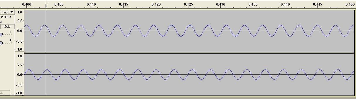
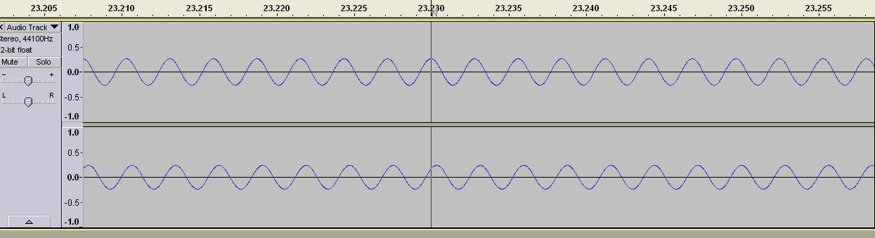
Here is a receiver phase verification. This is with a single antenna on both
receiver channels. In order to do any useful phase tests, the receiver system
has to be phase stable between channels in this test:
Start time = 0.4 seconds
Mid time = 22.23 seconds
End time = 56.9 seconds
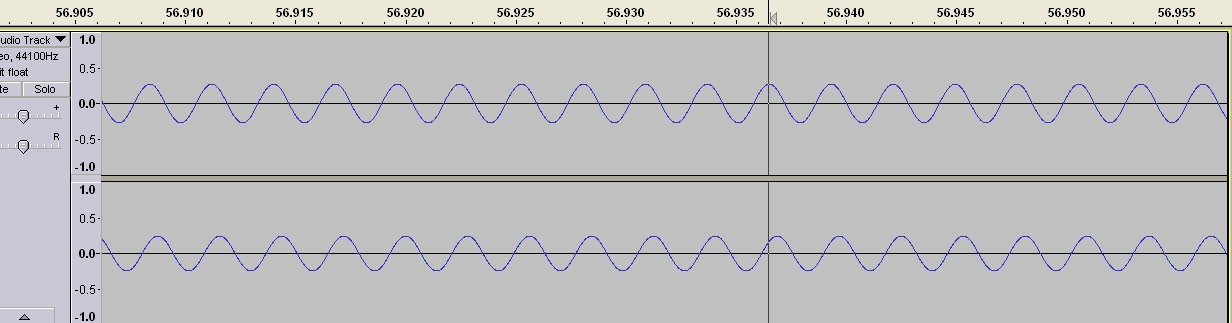
Careful examination of phase with a common antenna used for both receivers
proves phase stability. There is no phase drift between channels
throughout the entire recording time. This test proved my RX channels are phase
stable, and any drift in phase is from the antennas.
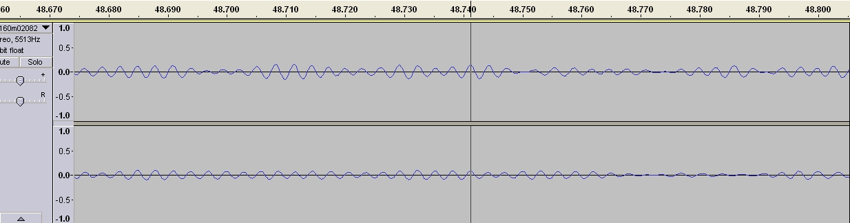
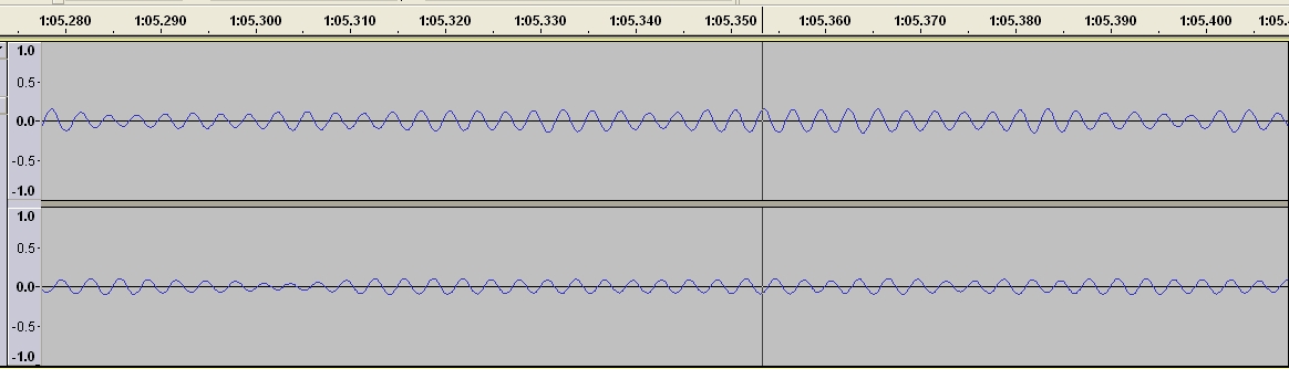
This picture below is from KH6AT at 48.74 seconds in recording time. Left (top) channel “rear” Beverage
pair 880-ft long x 350-ft spacing wide, right (bottom) channel “front”
Beverage pair 880-ft long x 330-ft spacing wide. Guessing about 1000-1200 feet
SW/NE (Echelon) stagger in these antenna pairs.
Notice two things occur below:
1.) One antenna does not always fade at the same time the other antenna fades
2.) The relative phase between antennas slowly rotates
KH6AT signals in-phase at this time:
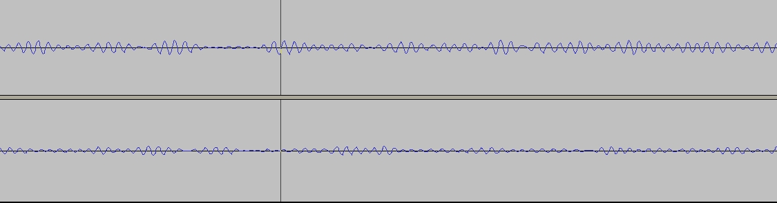
KH6AT at 1 min 5.35 seconds into the contact is 180 degrees out-of-phase on
channels:
180-degrees phase drift occurred over a time period of ~45 seconds. The
drifting or rotating phase is why I cannot directly combine my large
antennas into one giant phased antenna. This is also at least partly why really
long antennas just don’t work well. If I make antennas really
long, they have more fading. I believe this is because the wave at different
areas of the antenna is slowly rotating in-and-out of phase. Clearly we can see
that spatial effect on KH6AT’s signal.
KH6AT sample signal
V and H Sample
Lack of directivity hampers S/N ratio, but here is a sample of a true
horizontally polarized antenna and a reference vertical at the same location.
Note the in-and-out fading is much faster in this comparison between a small
horizontal loop at 280-feet, and a vertical wire up along the same supporting
tower as a vertical. This signal is a steady carrier on 1820 kHz, unknown
skywave source (but almost certainly a AM BC station harmonic to the northwest
of me).
This is probably caused by a slow rotation of polarization, since the
antennas are essentially at the same physical point.
I need to get stronger recordings of this.
Recorded sample of carrier
|

